


High-voltage Circuit Breaker Double-terminal Grounding Action Characteristic Testing System
Product Introduction
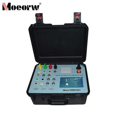
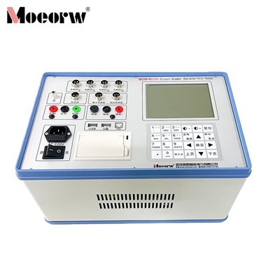
MOEORW-W5130D High-Voltage Circuit Breaker Dual-End Grounding Action Characteristic Testing System, designed in accordance with national and power industry standards, is suitable for various high-voltage circuit breakers and related equipment. Featuring multi-type sensor compatibility and multi-parameter synchronous measurement capabilities, it offers user-friendly operation and strong anti-interference performance. The system accurately performs mechanical characteristic testing, low-voltage tests, and other functions, while supporting data storage and export. It provides reliable assurance for the safe operation of power systems.
Product Parameter (specification)
|
Time measurement |
|
|
Route 12 Inherent opening (closing) time Different phases within the opening (closing) switch The time difference between phase opening (closing) (1 ~ 99 ms ) |
|
|
Closing (opening) bounce time (number of bounces) |
|
|
Different testing time range;1 ms to 99 ms, resolution;0.01 ms ; Internal trigger test range;1 ms ~ 999 ms , resolution;0.01 ms . 1000ms ~ 9999ms, resolution;0.1ms ; 10000ms ~ 200000ms , resolution;1ms . |
|
|
External trigger test range |
0.01 ms ~ 200 s |
|
Accuracy within 1000 ms |
0.05% ± 0.1ms |
|
Measurement of closing resistance |
3 ( 6 ) Circuit inherent opening (closing) time Different phases within the opening (closing) switch Phase-to-phase disconnection (closing) Closing resistor connection time and resistance value |
|
Measurement range |
30 ~ 10000 Ω, resolution;0.1Ω , accuracy;≤ 1 % ± 2 digits |
|
Graphite contact measurement |
3/6- channel inherent tripping (closing) time (optional) Different phases within the opening (closing) switch Phase-to-phase disconnection (closing) Measuring current;10A |
|
Measurement of double-ended grounding switch |
3 (6) Circuit inherent opening (closing) time Different phases within the opening (closing) switch Closing (opening) bounce time and waveform |
|
Dynamic resistance measurement |
1 channel, current 200A, measurement range;-50 mΩ , accuracy;≤ 0.5% ± 0.5 uΩ . |
|
Velocity Measurement |
Velocity at instantaneous separation (or instantaneous engagement) Average speed over a specified time period (travel segment or angle segment) |
|
Speed measurement range |
0.01~ 20.00m /s for 0.1mm sensor. 345° angle sensor, 0.01~ 20.00m /s. Laser sensor range;0.01–15.00 m /s . |
|
Stroke Measurement |
Moving Contact Stroke ( 3-channel stroke measurement optional) Contact travel (opening distance) Over-trip Overshoot or rebound |
|
Measurement range |
Linear sensor;50mm, Measurement range;0-50mm, Resolution;0.1mm . Rotary sensor;345 ° , measuring range;0-1000mm, resolution;0.08 ° . This sensor has a 15-degree ineffective zone. During installation, the effective area of the sensor should be visible on the instrument, and the reading should ideally be around 160-200 degrees. Accelerometer measurement range;0-300mm, resolution;0.1mm . (Optional) Coil current measurement range;maximum current 30 A , resolution;0.01 A. Coil resistance measurement range;0 ~ 2000Ω , resolution;0.01Ω. Instrument power supply;AC 220V ± 10% ; 50Hz ± 2 % |
|
DC power supply |
DC6 ~ 270 V continuously adjustable, DC24V≤15A (short time), DC220V≤20A ( short time) . |
|
External trigger voltage |
AC/DC 10-300V, current ≤120A |
|
Measurement range of disconnecting switch |
(1) Voltage output;DC 6 ~ 270V (adjustable); (2) Power output time;0.01-20 seconds (adjustable); (3) The maximum acquisition time for the break point signal is 200 seconds ; (4) It can measure the closing and opening time of the circuit breaker, the three-phase asynchrony, the bounce time and number of times. |
|
Main unit dimensions |
380×280×170mm |
|
Operating environment |
-30 ℃ to +50℃ Relative humidity;≤90% |
Product feature and application
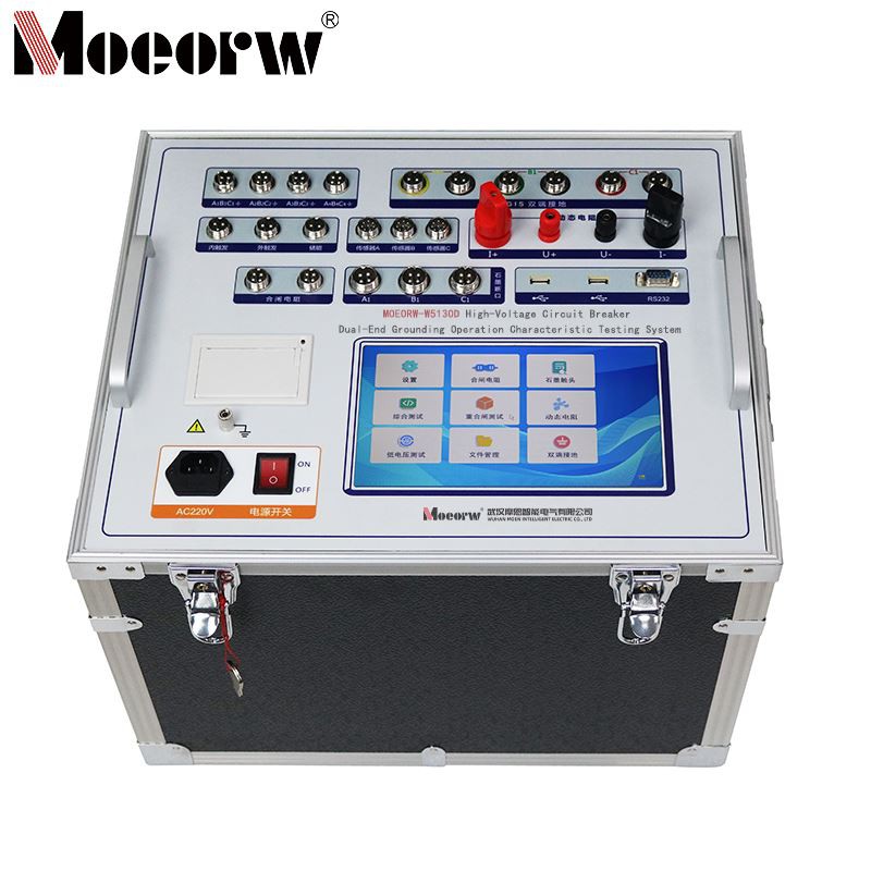
⑴ This instrument is an embedded industrial control computer featuring a Cortex™-A8-based motherboard with a 1GHz clock speed and 1GB flash memory, booting up in just 16 seconds. Its 9-inch color display runs Windows OS with an intuitive, user-friendly interface. The touchscreen supports both Chinese and English input, facilitating on-site operation.
⑵ Equipped with a high-speed thermal printer for convenient on-site printing of test data.
⑶. Integrated operating power supply eliminates the need for an external secondary power source, ensuring convenient and efficient operation. It provides an adjustable DC power supply ranging from 6V to 270V with a current of 20A. The operating voltage for both closing and opening coils can be freely set, and it can perform low-voltage operation tests on circuit breakers.
⑷ Equipped with linear sensors, rotary sensors, universal sensors, laser sensors (optional), mounting brackets, and specialized multi-functional connectors for extremely convenient and straightforward installation.
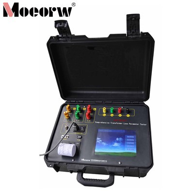
⑸ Applicable to all models of SF6 switches, GIS assemblies, vacuum switches, and oil switches manufactured domestically and internationally.
⑹. Obtains all data and graphs with a single switch operation. Test data and graphs display simultaneously on the screen. Speed can be recalculated without retesting. Displays various switch/circuit breaker curves: closing travel curve; opening travel curve; close-open travel curve; open-close-open travel curve; coil current curve; motor energy storage curve; time curve. Performs numerical and graphical curve analysis.
⑺ The main unit stores 30,000 sets of test data (expandable via memory card) with an internal real-time clock for convenient archiving.
⑻ Equipped with 2 USB ports for mouse operation, direct data saving to USB drives, and uploading to computers for analysis/storage. Optional RS232 interface for network operation and optional WiFi operation.
⑼. Simultaneously measures: 12 metal contact break points, 6 main break points and 6 auxiliary break points, 3/6 closing resistances, 3/6 graphite contact tests, 3/6 dual-end grounding (3-channel or 6-channel optional), 1 dynamic resistance channel, and 1 speed channel (3-speed channels optional). Measures circuit breaker travel, overtravel, rebound, and overshoot.
⑽. Incorporates envelope analysis: generates standard envelopes using built-in circuit breaker reference data for comparative analysis, and performs switch vibration frequency analysis.
⑾. Internal anti-interference circuitry ensures reliable operation within 500kV substations.
⑿. Dual-end grounding function employs high-frequency measurement clamps utilizing unique frequency conversion technology. Operating at frequencies exceeding 10kHz (with phase-specific frequencies) and currents up to 1A, it precisely measures circuit breaker closing/opening times, bounce duration, and bounce frequency.
⒀. Loop and dynamic resistance measurements utilize 200A high-current and high-precision displacement sensors to measure static and dynamic resistance of circuit breakers, analyzing arc contact conditions.
Prodection details
Suitable for various high-voltage circuit breakers (including low-oil, multi-oil, vacuum, SF6, GIS integrated units, etc.) and disconnect switches in power systems, as well as earthing switches. It can perform mechanical characteristic parameter testing, low-voltage tests, dynamic resistance measurements, and more in scenarios such as substations (including 500kV level) and power maintenance sites, meeting equipment operation and maintenance as well as performance verification requirements.
Company Qualifications
Hot Tags: high-voltage circuit breaker double-terminal grounding action characteristic testing system, China high-voltage circuit breaker double-terminal grounding action characteristic testing system manufacturers, factory, Circuit Breaker Analyzer CB Analyzer, High voltage Circuit Breaker Double terminal Grounding Action Characteristic Testing System, Circuit Breaker Characteristic Analyzer, High Voltage Switching Time Characteristic Tester, circuit breaker analyzer, Circuit Breaker Dynamic CharacteristicTester