Carrier-based Wireless Secondary Voltage Drop Load Tester
Professional power metering and testing equipment, specializing in carrier-based wireless secondary voltage drop load testing, providing a one-stop solution for all power metering testing needs.
Carrier communication over 1 kilometer, eliminating the need for temporary cables, multiple synchronization methods, accurate wiring identification, massive data storage, and easy operation.
Power metering on-site verification, PT/CT secondary circuit testing, wiring fault diagnosis, metering personnel training, and other power operation scenarios.
Product Introduction
The MOEORW-W8107 carrier-based wireless secondary voltage drop load tester utilizes a general-purpose instrument and software platform independently developed and owned by our company. The hardware platform integrates a 32- bit CPU , a 100M high-speed DSP , a 100,000 -gate FPGA , a 10M network control chip, standard USB flash drive storage, and a color LCD interface. The software platform integrates an embedded real-time operating system ( NSRTOS ), an advanced graphical user interface ( NSGUI ), a file management system ( NSFILES ), and a TCP/IP network protocol stack ( NSNET ).
A series of new processes and technologies have been adopted in both hardware and software, making the instrument smaller, more reliable, more stable in performance, easier to use, and more functional.
The MOEORW-W8107 carrier-type wireless secondary voltage drop load tester is our company's latest improved third-generation product based on years of experience in producing wireless secondary voltage drop and field calibration instruments. It adopts transformer secondary line carrier communication technology, and compared with previous generations of products, it completely solves the shortcomings of voltage drop testing affected by complex environments such as weather and tall buildings when using GPS and ISM wireless as synchronous sampling signals.
This product uses high-impedance input technology for carrier communication, which does not affect the accuracy of power metering during operation, and the communication distance is greater than 1 kilometer.
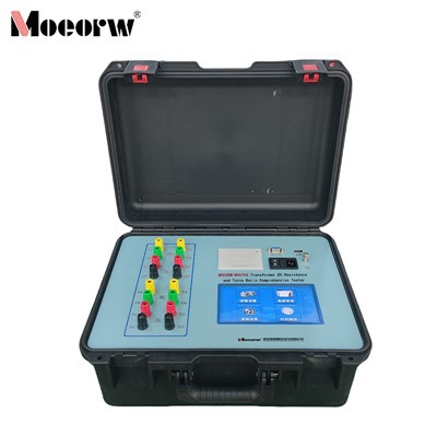
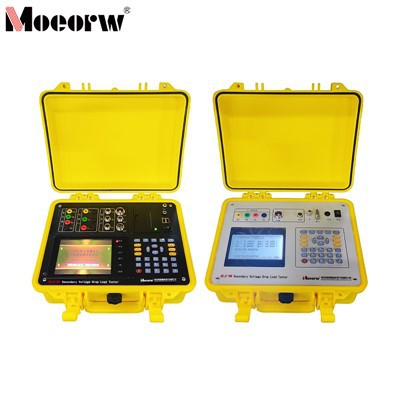
The secondary voltage drop measurement consists of two parts : a main unit and an auxiliary unit. The main unit automatically completes the measurement of the secondary voltage drop by transmitting a synchronization signal. There is no need to run a temporary cable between the electricity meter side and the PT terminal. From the testing principle, this eliminates the possibility of power grid accidents caused by running cables. It ensures the accuracy of electricity metering and does not affect the safe and stable operation of the power grid. It solves the problem of large workload and easy accidents when using traditional PT secondary circuit voltage drop testers .
Product Parameter (specification)
Product features and applications
- The 9-inch 1024×480 resolution color touch screen display allows for the setting of the parameters of the calibrated meter, display of electrical parameters, vector diagrams, wiring identification results, and the error of the calibrated meter all on one screen under the comprehensive testing function.
- It adopts a graphical user interface similar to Windows, with pure touchscreen operation, making it simple to use.
- It has a built-in handwriting input function, allowing English words to be entered by handwriting and numbers to be entered via the numeric keypad.
- The intelligent help system provides users with operation methods at any time.
- The sampling synchronization signal can be synchronized in three ways: wireless, carrier, and cable, which are suitable for different operating environments.
- The carrier communication uses high-impedance input technology, which does not affect the accuracy of power metering during operation, and the communication distance is greater than 1 kilometer.
- It has a wiring error detection function and can display the voltage phase sequence diagram of the meter terminal and PT terminal to determine the correctness of the wiring.
- It can perform fully automatic measurements in three-phase three-wire, three-phase four-wire, and single-phase modes, and automatically calculate the ratio difference, angle difference, voltage drop, and overall error of the three phases .
- No need to disconnect the secondary circuit; use a clamp meter to measure CT and PT loads safely and quickly.
- It can perform on-site testing of single-phase active energy meters, three-phase three-wire active energy meters, three-phase four-wire active energy meters, three-phase three-wire reactive energy meters, and three-phase four-wire reactive energy meters, and can also perform standard deviation testing .
- It has the function of verifying the fundamental frequency table and harmonic frequency table, and can verify the fundamental frequency table and harmonic frequency table .
- It can simultaneously verify the main and auxiliary meters, and perform active and reactive power verification on the same energy meter at the same time.
- An optional wireless pulse sampler can be installed, placing the field calibrator at the current transformer end and transmitting the data remotely at the energy meter end using a wireless pulse transmitter. The error obtained in this way is the total error of the metering secondary circuit, which includes the energy meter error and the secondary voltage drop error.
- It can simultaneously display the real-time measurement waveforms of three-phase voltage and three-phase current .
- It can analyze the harmonic content of voltage and current in any phase in real time, and display the harmonic data of voltage and current on one screen in a bar chart; it can measure the effective value, phase angle, active power and reactive power of voltage and current from the 1st to the 51st harmonic to determine the power flow direction of each harmonic; it can add up the positive and negative power of all harmonics separately and display the percentage with the fundamental frequency .
- It can identify 2256 types of incorrect three-phase three-wire and 18432 types of incorrect three-phase four-wire wiring; it provides corresponding wiring diagrams and wiring coefficients based on the wiring results; it performs electrical correction calculations for incorrect wiring; it simulates various incorrect wiring in the field and provides corresponding wiring diagrams, phasor diagrams, and wiring coefficients for use in metering personnel training. Low loads (less than 1mA) do not affect the wiring identification results.
- It has a function to compensate for incorrect three-phase three-wire wiring.
- It has an energy accumulation function, and two devices can be used together to measure line loss .
- The instrument has a built-in temperature and humidity sensor, eliminating the need for an external temperature and humidity sensor.
- It can detect 485 communication faults in electronic energy meters .
- It features 485 automatic meter reading functionality. It meets the requirements of the "On-site Operation Guidelines for Electricity Metering Devices" issued by the State Grid Corporation of China and saves the data. It can read data from meters that comply with the 97 and 07 communication protocols.
- The brightness of the LCD screen can be adjusted.
- It can use a standard USB flash drive to store on-site test data, and can save more than 300,000 on-site test records.
- It has a built-in high-capacity storage chip that can store on-site test data, with a capacity of over 200,000 records.
- You can create or open existing field record library files, and perform operations such as deleting and querying records in the library files.
- The comprehensive data browsing function enables data interaction between the calibrator's memory and the USB flash drive.
- It has four built-in user-defined calibration parameters, making it easy to connect with various MIS systems.
- The management PC can read the field test records from the calibrator, and a USB flash drive can be directly plugged into the USB interface to read them; the PC can also write the information of the energy meter to be calibrated to the USB flash drive, realizing on-site input-free operation.
- The device can be directly plugged into the USB port of a PC, and the PC can read the field test records in the calibrator; alternatively, the information of the electricity meter to be calibrated can be written into the device's memory through the PC, achieving on-site input-free operation.
- An optional scanner can be installed to read the electricity meter information in the verification plan by the electricity meter barcode number .
- It has comprehensive overvoltage and overcurrent protection measures, making it safe and reliable.
- It features built-in external power supply switching and protection functions for convenient on-site operation; an optional built-in lithium battery with battery capacity display is also available .
- The voltage and current ranges can be switched manually or automatically, and the energy constant remains unchanged across the entire range.
- This switching power supply uses a wide input voltage range of AC30V to 450V, making it highly adaptable and safe and reliable.
Prodection details
Electricity meter field verification:
Verifies single-phase/three-phase active/reactive and fundamental/harmonic electricity meters, supporting simultaneous verification of main and auxiliary meters, and active and reactive power.
PT/CT secondary circuit testing:
Measure the PT secondary voltage drop and PT/CT secondary load to obtain key parameters such as ratio difference, phase difference, and impedance.
Troubleshooting wiring faults:
Identify incorrect three-phase three-wire/four-wire wiring, calculate correction factors, replenish electricity charges, and troubleshoot metering wiring issues.
Electricity metering analysis:
Detecting 1st to 51st harmonics, voltage and current waveforms, measuring line losses, and analyzing the impact of harmonics on metering.
Smart meter reading and equipment testing:
485 / Infrared automatic meter reading, with optional current transformer ratio and energy meter clock verification functions.
Metrology training and practice:
Simulate various incorrect wiring errors to generate phasor diagrams/wiring diagrams for practical teaching of metrology personnel.
Company Qualifications
Q: Are you a factory or a trading company?
We are a professional manufacturer of testing equipment.
Q: How is the after-sales service?
A: The warranty period is 12 months. After the warranty period, we also provide lifetime service paidrepair or service.
Q: How is the after-sales service?
A: The warranty period is 12 months. After the warranty period, we also provide lifetime service paidrepair or service.
Q: What about transportation?
A: It depends on your requirements. We can ship to your airport by air, to your seaport by sea, or to your office by courier.
We also accept cooperation with your shipping agent.
Q: Are your keyboard, interface, software, and manuals in English?
A: Yes, if you are using the English version of the keyboard, interface, software, and manual and require other languages, please contact us for confirmation.
Hot Tags: carrier-based wireless secondary voltage drop load tester, China carrier-based wireless secondary voltage drop load tester manufacturers, factory, ct pt analyzer, Fully Automatic Transformer Calibration Bench, Transformer Field Calibrator