


Secondary Voltage Drop Load Tester
Product Introduction
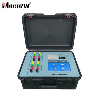
Our firm carefully researched and produced the Wireless Secondary Voltage Drop/Load Tester, a cutting-edge, intelligent wireless testing device that measures the secondary voltage drop and load of voltage transformers automatically. By doing away with the necessity for long voltage test cables and drastically lowering the possibility of PT secondary short-circuit events, it totally replaces traditional secondary voltage drop/load testers. This makes it possible for substations to operate safely. The device does not require satellite acquisition because it uses non-GPS wireless synchronization. It provides quick testing speeds that are independent of topography.
This device has many advantages, including its small size, light weight, good stability, high measurement precision, and simple operation. Work efficiency is significantly increased by its straightforward wiring, practical testing, and recording features. It provides an easy-to-use human-machine interface for quick and easy operation with its large-screen true-color graphic LCD display, graphical menu operation with Chinese prompts, and multi-parameter display interface. All levels of power users favor this product.
Product Parameter (specification)
|
1. Usage Environment |
(1) Ambient temperature: -10℃~ 40℃ (2) Relative humidity: ≤80% |
|
2. Measurement accuracy |
The measurement accuracy of this instrument is Class 1. |
|
Host parameters |
|
|
Voltage |
0.05 level |
|
Current |
0.2 level |
|
Power |
0.2 class |
|
Phase angle |
0.05° |
|
Extension parameters |
|
|
Voltage |
0.05 level |
|
Phase angle |
0.05° |
|
Overall parameters |
|
|
Difference |
Δf = ± (1% × f + 1% × δ) ± 0.01 (%) |
|
Angle difference |
Δδ=±(1%×δ+1%×f) ±1 (minutes) |
|
Conductivity |
G = ± (1% × G + 1% × δ ± 0.01) mS |
|
Susceptance |
δ = ± (1%×δ+1%×G±0.01)mS |
|
Load |
S = ± (1% × S ± 0.1)VA |
|
Resistance |
R = ± (1% × R + 1% × X ± 0.1) Ω |
|
Reactance |
X = ± (1%×X + 1%×R ± 0.1)Ω |
|
3. Charging power supply |
AC 176V~264V, frequency 45-55Hz |
|
4. Measurement range and resolution of the instrument |
|
|
Test Project |
scope |
minimum resolution |
|
Voltage measurement range (V) |
40~120,000 |
0.001 |
|
Current measurement range (A) |
0.005~6 |
0.0001 |
|
Comparison Difference (%) |
-10.000~10.000 |
0.001 |
|
Angular difference (ˊ) |
-600~600.00 |
0.01 |
|
Error value (%) |
-10.000~10.000 |
0.001 |
|
Revision (%) |
-10.000~10.000 |
0.001 |
| Insulation: |
⑴ The insulation resistance between the voltage and current input terminals and the casing is ≥100MΩ . (2) The working power input terminal withstands 2KV (RMS value) of power frequency between itself and the casing for 1 minute. |
|
| Battery working time: | More than 6 hours after a full charge. | |
| Volume: |
Main unit: 32cm×24cm×13cm Extension unit: 32cm×24cm×13cm |
|
| Weight: |
Main unit: 2.5 kg Extension: 2 kg |
|
Product feature and application
1. Automatically measures the secondary voltage drop of three-phase three-wire or three-phase four-wire voltage transformers via wireless transmission, eliminating the need for lengthy voltage test cables between the instrument and remote test points. This prevents unnecessary short-circuit faults caused by excessively long wiring.
2. Non-GPS synchronization method requires no satellite acquisition, ensuring quick and convenient operation.
3. Automatically calculates three-phase ratio error, phase angle error, and total error.
4. Automatically measures load in the secondary circuits of voltage and current transformers.
5. Automatically detects and stores measurement error data caused by test leads under various wiring configurations, applying automatic corrections in subsequent tests.
6. Features specially designed software correction functionality, enabling precision adjustments without hardware modifications. Field verification is achievable at all levels of power testing and research departments.
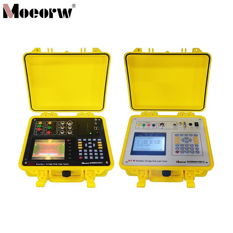
7. Simultaneously displays various electrical parameters on a single screen, including voltage, current, phase angle, power factor, active power, reactive power, and apparent power. Waveform diagrams for each phase parameter can be displayed.
8. Features harmonic measurement capability, capable of measuring voltage and current harmonics up to the 32nd order.
9. Incorporates a high-capacity rechargeable battery pack for operation without external 220V AC power in outdoor settings. Includes a built-in rapid automatic charger for quick battery replenishment.
10. Battery remaining capacity percentage indication, not merely a low-battery alarm.
11. Large-screen, high-brightness true-color LCD display with fully Chinese graphical menus and operation prompts for user-friendly interaction. Conductive silicone keys simplify operation. Wide-temperature LCD with automatic contrast and brightness adjustment adapts to all seasons.
12. Users can print test results anytime via a micro printer.
13. Test result storage function, capable of storing 200 sets of test data.
14. Equipped with backend management software to upload stored records to a computer for centralized management.
Prodection details
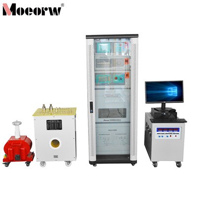
This device is used for PT/CT secondary circuit voltage drop and load detection, troubleshooting metering issues, routine inspections, and field calibration at outdoor areas without mains power. It is appropriate for substations and industrial/commercial user metering sites.
Company Qualifications
Hot Tags: secondary voltage drop load tester, China secondary voltage drop load tester manufacturers, factory, ct pt analyzer, Fully Automatic Transformer Calibration Bench, Transformer Field Calibrator