


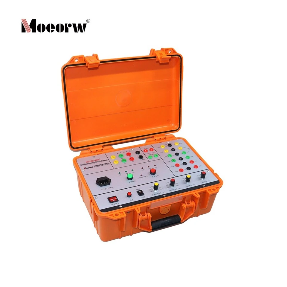

Intelligent Analog Circuit Breaker
Product Overview
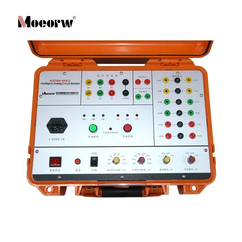
The MOEORW-WKM11 intelligent simulated circuit breaker is developed based on Field Programmable Gate Array (FPGA) and protected power electronic components with independently separated trip/close coil loop design, dedicated to substitute physical high-voltage circuit breakers during whole-set transmission test of relay protection and automatic power system devices. This equipment precisely replicates operational characteristics of single-trip-coil circuit breakers supporting 3-phase or split-phase switching action within 6kV–110kV voltage classes. Unlimited switching operations eliminate abrasion and mechanical fatigue of real HV breakers during repeated laboratory and field commissioning tests, improving testing completeness and accuracy for power grid operators, industrial power users, academic institutes and relay protection manufacturers. It realizes configurable trip/close duration, adjustable coil equivalent resistance and breaker failure simulation to cover comprehensive protection verification including three-phase reclosing, single-phase reclosing and breaker failure protection trial.
Technical Specifications (Standard International Unit Table)
| Item Category | Parameter Details |
| Main Working Power Supply | AC 220V ±10%, 50Hz; operating current <0.5A |
| Trip & Close Control Rated Voltage | DC 48V ~ DC 220V |
| Selectable Trip Time | 20/30/40/50/60/70/90/110ms; tolerance: ±5ms |
| Selectable Close Time | 40/60/80/100/200/300/400/500ms; tolerance ≤±5ms (≤±20ms @500ms setting) |
| Trip Coil Adjustable Resistance | ∞Ω,100Ω,200Ω,400Ω |
| Close Coil Adjustable Resistance | ∞Ω,100Ω,200Ω,400Ω |
| Auxiliary Contact Rated Capacity | DC 220V/0.5A; AC 220V/5A |
| Independent CB Position Output Contacts | Total 12 pairs, grouped into two sets corresponding to trip coils |
| Manual Switch Auxiliary Contacts | 1 pair self-hold close contact for manual closing; manual tripping contact delays 60ms reset after button release |
| Breaker Failure Logic | No switching action upon trip command; trip/close supply cuts after 1s delay, circuit recovers full current after additional 20s |
Core Product Features (Logic: Hardware Design → Performance → Practical Application Value)
3.1 Hardware & Circuit Design
1. Adopts full FPGA digital control architecture and surge-protected power semiconductor circuits; each trip/close coil is assigned to an independent electrical loop to avoid phase-to-loop cross interference during split-phase test.2. Front-panel modularized configuration knobs and select switches: independent selector for 3-phase/single-phase operation mode, separate rotary switches for time and resistance calibration; LED indicator grouping for phase closing/tripping status, manual operation and breaker failure status.3. Built-in 12 groups of mutually isolated auxiliary position contacts plus dedicated hand-close/hand-trip signal contacts to fully mimic physical breaker auxiliary secondary wiring without external relay expansion.
3.2 Core Performance Advantages
1. Precise time grading: fixed discrete time gears for trip/close with tight factory-calibrated time tolerance to reproduce actual HV breaker mechanical operating delay accurately.2. Continuously adjustable equivalent coil resistance matches real DC operating coil impedance of field-installed breakers, enabling authentic coil current simulation under protection outlet excitation.3. Dedicated breaker failure simulation module realizes fixed 1s delayed power cut & 20s automatic recovery cycle for standard failure protection verification without extra peripheral circuit modification.
3.3 Practical On-site Value
1. Avoid repeated mechanical switching of expensive 6~110kV real circuit breakers during whole-set transmission test, extending service lifespan of field primary equipment drastically and cutting maintenance cost for end users.2. Supports three independent single-phase CB simulation under single-unit chassis: configure each phase as an individual three-phase breaker to finish multi-set protection synchronous testing, improving laboratory testing throughput.3. Manual operation contact self-locking & delayed reset design directly satisfies non-correspondence reclosing startup and manual trip discharge verification of auto-reclosing devices, matching standard protection test workflow.
Working Principle
The core digital control unit based on FPGA receives external trip/close command signals either from front-panel manual pushbuttons or secondary outlet signal of external relay protection device. After pre-set delay time (configured via panel time selectors), internal relay drives corresponding auxiliary contact groups to change open/closed status to simulate breaker switching action. When resistance is adjusted via impedance knobs, passive fixed resistors are connected into simulated coil loop to modify loop operating current, matching actual field coil load characteristic. Upon breaker failure button activation, internal control logic locks all switching output; energized coil loop remains powered for preset 1s before automatic disconnection and restores after 20s standby cycle to replicate breaker mechanical reject action during failure protection test.
Application Fields
- Power Grid Industry: Provincial/municipal power supply bureau relay protection commissioning, substation secondary circuit whole-set transmission test for 6~110kV switchgear bay· Heavy Industrial End-users: Mining, metallurgy, chemical enterprise self-owned power plant protection cabinet verification· R&D & Education: Electrical engineering university laboratory, relay protection manufacturer R&D lab for new protection prototype testing· Third-party Test Institution: Power equipment type test & acceptance inspection of protection automation devices
Applicable Standards & Compliance
Designed and tested referring to domestic & international power secondary equipment test specifications for relay protection transmission experiment; meets field wiring requirements of IEC 61850 secondary circuit auxiliary contact configuration and GB/T standard for HV breaker secondary control circuit testing. Manufactured by Wuhan Moen Intelligent Electric (Mocorw), certified per enterprise internal factory calibration standard for power test instrument.
Standard Accessories (from official manual)
1. AC220V mains input power cord (1pc)2. Multi-core insulated connecting wire set for A/B/C phase trip/close coil wiring (1 set)3. Operation instruction manual (English + Chinese version)4. Terminal wiring schematic diagram for whole-set test matching relay tester
Routine Maintenance Guidance
1. Pre-operation inspection: Confirm AC input power within specified ±10% tolerance range before powering on; check all panel select switches stay at fixed gear without intermediate floating position
.2. Monthly maintenance: Clean front-panel switch dust with dry anti-static cloth; avoid liquid penetration into terminal socket and coil wiring terminals.
3. Long-term idle storage: Cut off main AC power supply, store under ambient temperature from -10℃~+45℃ with relative humidity ≤95% non-condensing environment.
FAQ (Application & Commissioning Troubleshooting Focused, Concise Answer)
Q1: Simulated breaker fails to switch after receiving protection trip/close command?
A: Verify corresponding coil wiring polarity and connection reliability; check resistance selector is not set to open-circuit ∞Ω mistakenly; confirm operation mode (3-phase/single-phase) matches actual wiring scheme.
Q2: Manual close button pressed but hand-close contact cannot self-hold?
A: Reset self-locking circuit by pressing manual trip button to release pre-locked status; inspect contact terminal wiring looseness on rear panel.
Q3: Breaker failure mode triggered yet coil current does not cut after 1s delay?
A: Restart device by power cycle; confirm failure indicator LED is flashing meaning failure function is correctly activated.
Hot Tags: intelligent analog circuit breaker, China intelligent analog circuit breaker manufacturers, factory, breaker tester, circuit breaker analyzer, Circuit Breaker Dynamic CharacteristicTester, High voltage Circuit Breaker Double terminal Grounding Action Characteristic Testing System, High Voltage Switching Time Characteristic Tester, HV Circuit Breaker Tester


