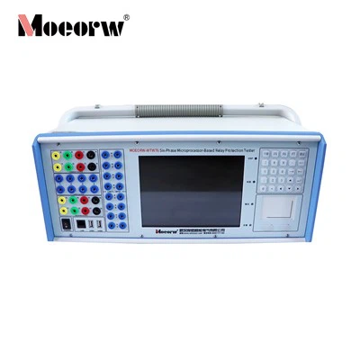
Product Overview
MOEORW-WTS45 optical digital relay protection tester is developed complying with DL/T 624-2010 Technical Conditions for Microcomputer-Based Relay Protection Test Devices and the full IEC 61850 communication standard system. It adopts dual PowerPC+X86 modular hardware architecture with integrated high-performance power amplifier, featuring compact volume, lightweight structure and high measurement precision.
This test platform supports full optical digital signal transceiving and analog quantity output, and integrates complete test modules for conventional & digital IEDs. It is designed for functional verification and performance calibration of merging units, relay protection devices, measurement & control units and intelligent terminals, widely deployed in power plants, transformer substations and electrical equipment R&D laboratories.
Core Technical Specifications
Synchronization & Timing Interfaces
|
Parameter |
Technical Index |
|
GPS/BD Antenna Port |
1 channel |
|
IRIG-B/PPS Optical Signal |
2 channels (1 for time synchronization, 1 for time output) |
|
IRIG-B/PPS Electrical Signal |
2 pairs (1 for sync, 1 for output) |
|
IEEE 1588 Port |
1 pair |
|
Supported Timing Protocols |
GPS/BD, IRIG-B DC, PPS, PTP 1588, NTP |
Communication Optical Interfaces
|
Item |
Specification |
|
IEC 61850 LC Optical Ports |
8 pairs (6×100M adaptive, 2×100/1000M adaptive) |
|
Optical Wavelength |
1310nm |
|
IEC 60044 ST Ports |
6 Tx + 2 Rx |
|
Supported Optical Protocols |
IEC61850-9-1/9-2, GOOSE, FT3, Extended FT3, DL/T 282 |
|
Serial Encoding |
UART: 2/4/6/8/10M Baud; Manchester:5/10/20M |
Wired & Human-Machine Interfaces
|
Parameter |
Value |
|
RJ45 LAN Ports |
2 × 100Mbps |
|
USB Interfaces |
3 |
|
Touch Display |
10.4-inch true-color touch LCD |
Power & Environmental Conditions
|
Item |
Index |
|
Input Power |
AC/DC 220V, tolerance: -20% ~ +15%, 47~65Hz |
|
Operating Temperature |
-10℃ ~ 50℃ |
|
Relative Humidity |
≤95%, non-condensing |
Hardware Protection
- Current source: open-circuit detection & alarm
- Voltage source: overload & short-circuit lockout
- Over-temperature & over-current hardware interlock protection
Main Technical & Functional Features
Hardware & Architecture Advantages
1.Modular PowerPC+X86 dual-core platform with independent amplifier boards, supporting parallel analog & optical digital signal output without mutual interference.
2.10.4-inch industrial touch screen for standalone local operation, independent of external PC.
3.Built-in WIFI + 4G wireless communication modules, supporting remote testing and offline project storage via USB drives.
4.Multi-type optical port compatibility (LC/ST) covering mainstream intelligent substation protocols, single-fiber transmit/receive supported with built-in optical power measurement function.
Digital Message Simulation & Analysis Capability
1.Simulate full abnormal digital signals: packet loss, sequence jump, transmission jitter, time delay deviation, quality bit error, maintenance flag activation, status virtual variation.
2.Concurrent transceiving of SV and GOOSE messages on single optical Ethernet port, independent GOOSE signal control channel.
3.SCL file (ICD/CID/SCD) full parsing, graphical virtual terminal display for intuitive data flow visualization.
4.PCAP format message recording & playback, COMTRADE fault waveform import and recurrence.
5.MMS client service built-in, supporting remote reading/writing of protection fixed values from all IEDs.
Comprehensive Automated Test Function
1.Editable reusable test templates; all test items can be combined into engineering files for batch re-test during routine maintenance.
2.One-click full automatic testing for local-mounted and digital relay protection without manual parameter reset.
3.Multi-dimensional scan modes: amplitude, phase, frequency, impedance, sequence component, power, with ramp & slip frequency automatic variable algorithms.
4.Integrated complete test suites covering general quantity test, relay characteristic test and special substation equipment calibration.
Software Tool Auxiliary Functions
1.MCU real-time monitoring module: real-time display of each board temperature and fan operating status, overheat early warning.
2.Multi-channel clock output tool, synchronous time signal distribution for up to 8 secondary devices simultaneously.
3.Binary I/O logic operation (AND/OR), support hard contact and GOOSE channel cross-binding for state sequence trigger.
4.Independent SOE high-precision test module with 1ms time resolution for sequence-of-event verification.
Complete Test Module Classification
General Test Modules
1.Voltage & Current Test: Group-based analog output mapping for multi-branch transformer primary/secondary simulation
2.Harmonic Test: 0~63 times harmonic superposition, harmonic braking characteristic test for differential relays
3.Ramp Test: Step variable test for action/return value calibration with forward & reverse scan
4.Slip Frequency Test: df/dt, dv/dt variation simulation for under-frequency/under-voltage load shedding
5.General Digital Test: Independent per-channel SV/GOOSE parameter adjustment, abnormal message injection
Relay Protection Dedicated Test Modules
Whole-set fault simulation, directional zero-sequence overcurrent, three-phase inconsistency, negative-sequence overcurrent, compound voltage blocking directional overcurrent, loss-of-excitation, over-excitation, distance protection, power frequency variation distance, auto-reclosing, impedance characteristic scanning, general bus differential, transformer two/three-winding differential (including inrush intermittent angle test).
Special Substation Test Modules
SOE timing verification, COMTRADE fault playback, fast bus transfer, ATS auto-switching, under-frequency/under-voltage load shedding, primary frequency modulation curve simulation, PCAP message replay, optical power detection, generator synchronizing parallel, exponential fault waveform, power system oscillation & oscillation-with-fault simulation.
Application Fields
1.Power Generation Plants: Generator excitation protection, transformer differential, synchronizing device calibration
2.Intelligent Conventional Substations: Merging unit, protection, intelligent terminal routine commissioning & maintenance
3.Electrical Equipment Manufacturers: R&D verification of digital relay, MU, measurement & control IEDs
4.Power Research Institutes: Power system fault simulation, protection algorithm research
5.Third-party Testing Institutions: Type test & acceptance inspection of substation secondary equipment
Applicable Industry Standards
1.DL/T 624-2010 Technical Conditions for Microcomputer-Based Relay Protection Test Devices
2.IEC 61850 Substation Communication Networks and Systems (9-1/9-2, GOOSE, MMS)
3.IEC 60044-7/8 Electronic Current/Voltage Transformers (FT3 protocol)
4.DL/T 282 Electronic Transformer Serial Communication Standard
5.IEEE 1588 Precision Time Protocol, IRIG-B Timing Standard
Standard Accessories
- Main unit MOEORW-WTS45×1
- LC single-mode optical fiber jumper
- ST FT3 optical cables
- Hard contact test leads
- AC/DC power cable
- USB flash drive (software & operation manual)
- Factory calibration report
- User operation manual (English & Chinese)
Software Installation & Upgrade Guide
Operating System Requirement
Compatible with Windows XP / Win7 / Win8 / Win10; installation on non-system disk is recommended for Win8/10 to avoid permission restrictions.
Lower Computer Firmware Upgrade Steps
1.Open "Device Manager" from main software toolbar to detect online testers in LAN.
2.Right-click target device and select Upgrade Firmware.
3.Select corresponding VxWorks / FPGA / Bootrom bin file.
4.Wait for file upload and Flash writing (power cut forbidden during writing).
5.Pop-up success prompt, restart tester to activate new firmware.
Network Configuration Adjustment
1.Modify IP: Enter device manager, right-click to edit device IP, ensure PC and tester are in the same network segment.
2.WIFI Setup: Access built-in router web page (default 192.168.0.254, admin/admin), adjust LAN subnet matching tester IP segment, modify SSID & password as required.
Daily Maintenance & Safety Instructions
1.Safety Operation Rules
- Do not align eyes with fiber TX port when power is on to prevent laser eye injury.
- Forbid analog wiring plug/unplug while power amplifier indicator lights up.
- Stop test immediately if abnormal alarm occurs and inspect wiring first.
- Disassembling without manufacturer authorization voids warranty service.
2.Daily Maintenance
Clean optical port dust regularly with fiber cleaning sticks to avoid signal attenuation. Check fan operation via MCU tool before each test; clean dust blocking air vents. Store in dry, dust-free environment without explosive gas surroundings.
3.Storage Requirement Long-term storage environment: 0~40℃, humidity ≤80%, avoid direct sunlight.
FAQ
Q1: Software cannot discover MOEORW-WTS45 device via wired LAN
A: Verify PC and tester IP belong to same subnet; check RJ45 cable connection; restart tester and refresh device list.
Q2 Optical digital message cannot be received normally
A: Check optical fiber integrity and optical power value via built-in optical power test function; confirm correct port mapping in test configuration and SCD control block binding.
Q3 Amplifier over-temperature alarm pops up during long-time test
A: Reduce continuous output current; check fan status in MCU tool; ensure equipment ventilation space is unobstructed.
Q4 After firmware upgrade, tester fails to boot
A: Re-upload complete VxWorks and FPGA firmware files; avoid power interruption during Flash writing process.
Q5 GOOSE binary I/O cannot trigger state switching
A: Complete hard contact/GOOSE channel binding in Test Configuration-Switch Quantity setting, enable AND/OR trigger logic before test execution.
Hot Tags: optical-digital relay protection tester, China optical-digital relay protection tester manufacturers, factory, 3 phase relay tester, 9 phase Microcomputer Relay Protection Tester, Handheld Optical Digital Relay Protection Tester, relay protection tester, Three Phase Relay Protection Tester Kit, Three Phase Secondary Current Injection Relay Test Set