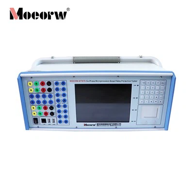
Product Overview
MOEORW-WTM53 is a full-function relay protection test platform developed in compliance with DL/T 624-2010 and IEC 61850 standard system, adopting dual PowerPC+X86 modular hardware architecture. The tester integrates analog output, digital optical communication signal transceiving, multi-mode time synchronization and automatic test functions, realizing unified testing of conventional secondary equipment and smart substation digital devices.
It supports synchronous output of analog AC/DC signals, SV sampling values, GOOSE control blocks and FT3 serial messages, and carries comprehensive test modules for relay protections, merging units, auxiliary automatic control devices. Equipped with built-in industrial touch screen and wireless communication modules, it is applicable to power plant commissioning, substation routine maintenance, electrical equipment R&D laboratories and power industry research institutions.
Core Technical Specifications
Analog Output Parameters
|
Parameter Category |
Technical Index |
|
AC Voltage Output |
Per channel 0–120V, 60VAAccuracy: ±4mV (0.2~2V); ±0.1% (2~120V)Resolution: 1mV |
|
AC Current Output |
Per channel 0–30A, max 450VAAccuracy: ±1mA (0~500mA); ±0.1% (0.5~30A)Resolution: 1mA |
|
Phase Angle |
Range: 0~360°, Accuracy ±0.1°, Resolution 0.1° |
|
Frequency |
0–1000Hz±0.001Hz (0–65Hz); ±0.01Hz (65–450Hz); ±0.02Hz (450–1000Hz)Resolution: 0.001Hz |
|
DC Voltage |
0–160V per channel, 60VA, accuracy ±0.2% |
|
DC Current |
0–20A per channel, 200VA, accuracy ±0.2% |
|
Small Signal I/O (Optional) |
12-channel analog input & output, -7V ~ +7V AC signal range |
Switching Quantity Interface
|
Item |
Specification |
|
Binary Input |
8 pairs, active/passive adaptive, DC 0–250V auto identification, channel isolation |
|
Binary Output |
6 pairs (2 fast-response channels, 0.1ms action delay), rated DC250V / 0.5A |
Digital Optical Communication Interfaces
|
Interface Type |
Configuration & Function |
|
IEC 61850 LC Optical Ports |
8 pairs total: 6×100M adaptive, 2×100/1000M adaptive, 1310nm wavelength, support SV9-1/9-2 & GOOSE transceiving |
|
IEC 60044 ST Serial Optical |
6 transmit ports + 2 receive ports, compatible with FT3 / extended FT3 / DL/T282 |
|
FT3 Baud Rate |
UART: 2M/4M/6M/8M/10M/15M/20M; Manchester:5M/10M/20M |
Synchronization & Communication Interfaces
|
Interface |
Parameters |
|
Time Sync Port |
GPS/BD antenna ×1; IRIG-B/PPS optical (sync + time broadcast); IRIG-B/PPS electrical; IEEE 1588 master/slave |
|
Wired Network |
Dual RJ45 100M LAN ports |
|
Wireless |
Wi-Fi + 4G remote test module |
|
USB |
3 universal USB ports |
Environmental & Power Specifications
|
Item |
Index |
|
Power Input |
AC/DC 220V, tolerance -20% ~ +15%, frequency 0 or 47–65Hz (DC optional) |
|
Operating Temp |
-10℃ ~ +50℃ |
|
Relative Humidity |
≤95%, non-condensing |
|
Display |
10.4-inch industrial touch LCD screen |
Main Hardware & Software Functional Features
Hardware Design Advantages
1.Modular Power Amplifier with multi-load switching logic Three output load modes (Light / Heavy / Extra Heavy) for AC/DC current output adjustment, with clear current limit thresholds for each mode to avoid hardware overload damage.
- Light/Heavy load: Max 18.3A single-channel AC, 9.16A single-channel DC
- Extra Heavy load: Max 14.2A single-channel AC, 7.14A single-channel DC
2.Multi-layer Safety Protection Circuit Built-in overheat, overcurrent, open-circuit protection for current source; overload & short-circuit protection for voltage source, with real-time MCU temperature and fan monitoring panel.
3.Integrated Multi-mode Synchronization System Supports GPS/BD, IRIG-B, PPS, IEEE1588 receiving and independent time broadcasting to 8 external devices simultaneously, compatible with all mainstream smart substation time synchronization schemes.
4.Dual Digital-Analog Signal Architecture Synchronized parallel output of hard-wired analog signals and optical digital messages, realizing one machine for conventional station and smart substation test work without extra auxiliary equipment.
5.Rich Optical Interface Configuration Supports single-fiber transmit/receive mode and built-in optical power measurement module, compatible with HFBR-57E5APZ (100M) & AFBR-5715APZ (1000M) optical modules.
Software Platform Capabilities
1.Visual SCD File Parsing & Virtual Terminal Mapping Import ICD/SCD/CID configuration files, graphically display virtual terminal data flow, support filtering by IED name/AppID, export mapping diagrams as images for engineering archiving. Global or individual control block maintenance tag configuration for test signal quality bit simulation.
2.Complete Standard Test Modules The software is divided into four major functional groups: General Test, Protection Test, Merging Unit Test, Special Test, covering all routine and special power system test items.
- General Test: Voltage & Current, Harmonic, Ramp, Slip frequency variation
- Protection Test: Full set of line, transformer, generator protection test functions including distance, differential, zero-sequence, loss-of-excitation, over-excitation, reclosing, oscillation blocking
- Merging Unit Test: Ratio & Phase error, time synchronization precision, transient characteristic test (digital-analog mixed exclusive function)
- Special Test: SOE, COMTRADE waveform replay, fast switch, ATS, primary frequency modulation, oscillation, digital-analog conversion, PCAP message playback, optical power measurement, synchronizing paralleling test
3.Abnormal Digital Message Simulation Simulate SV/GOOSE failure states including quality invalid, frame jitter, packet loss, sequence jump, maintenance mode, state false variation, delay deviation, for secondary device anti-interference verification.
4.Automatic Test & Project Management Custom editable test templates, save complete test projects for repeated on-site fixed-period inspection; one-click full automatic test of single protection device without repeated parameter input.
5.Message Capture & Analysis Tool Real-time capture SV/GOOSE/FT3 messages, store data as standard files compatible with ZHNPA analysis software, support offline waveform review and test report export.
6.Firmware & Network Management Built-in device manager for real-time monitoring of tester IP, serial number, synchronization status; support remote lower-computer firmware upgrade, IP address modification and Wi-Fi parameter configuration via wired Ethernet.
Application Fields
1.Power Grid Operation & Maintenance Routine inspection, fault diagnosis and acceptance of conventional station relay protections, smart substation merging units, intelligent terminals, measurement & control devices.
2.Power Generation Industry Generator loss-of-excitation, over-excitation, primary frequency modulation, synchronizing paralleling and transformer differential protection commissioning.
3.Equipment Manufacturers Performance verification of digital protection, MU, fast switching, ATS and other secondary automation equipment in laboratory R&D and factory delivery inspection.
4.Scientific Research & Educational Institutions Power system dynamic simulation, fault recurrence, anti-interference performance research and power major teaching experiments.
5.Industrial Power Plants & Metallurgy/Mine Enterprises Self-provided power station secondary protection device periodic calibration and overhaul work.
Compliant Standards
1.Domestic Industry Standard: DL/T 624-2010 Technical Conditions for Microcomputer Relay Test Equipment
2.International Communication Standard: Full compliance with IEC 61850 (9-1/9-2, GOOSE, MMS, IEEE1588), IEC 60044-7/8, DL/T 282 FT3 protocol
3.Power Test Regulation: DL/T 995-2016 Inspection Regulation for Relay & Grid Automatic Devices
4.Electrotechnical Terminology Standard: GB/T 2900.17 (IDT IEC 60050-447)
Standard Accessories
1.Main MOEORW-WTM53 test unit ×1
2.Optical fiber patch cords (LC/ST matching) set
3.Analog voltage/current test wires
4.Binary input/output wiring harness
5.GPS/BD timing antenna
6.Power supply cable
7.USB flash drive (pre-installed upper computer software, operation manual)
8.User operation manual, factory calibration certificate
Daily Maintenance Guidelines
1.Optical Port Protection Cover unused optical ports with dust caps; do not look directly at optical transmit ports when the tester is powered on to avoid eye damage. Clean fiber end faces with special optical alcohol wipes before connection.
2.Power Amplifier Operation Rules Stop all analog wiring operations when the power amplifier indicator light is illuminated to prevent electric shock or module burnout.
3.Storage Environment Store in dry, dust-free indoor environment; avoid long-term placement in high temperature, explosive gas or heavy dust industrial sites.
4.Firmware Upgrade Notes Keep stable wired Ethernet connection during lower-computer upgrade; power-off during writing firmware will cause device failure. The PC and tester must be in the same IP subnet.
5.Long-term Shutdown Maintenance If idle for more than 3 months, power on the tester for at least 2 hours monthly to activate internal circuit boards and avoid component damp failure.
Troubleshooting Common Failures
Q1: Tester cannot connect to upper computer software
A. Check PC and tester IP segments are consistent; confirm RJ45 cable intact. Restart the tester and refresh the device manager list; verify no firewall blocks port communication.
Q2 Optical message receiving shows synchronous flag abnormal (red mark)
A. Check timing antenna connection, reconfigure PTP/IRIG-B synchronization parameters; verify MU clock source setting matches tester broadcast signal.
Q3 Analog current output reports open-circuit alarm
A. Inspect current loop wiring for disconnection or loose terminals; re-connect test leads tightly before restarting output.
Q4 Software fails to import SCD file correctly
A. Confirm SCD/ICD file version compatibility; eliminate file damage, re-parse and refresh virtual terminal mapping list.
Q5 Firmware upgrade interrupted and equipment unresponsive
A. Contact manufacturer professional maintenance team, do not disassemble the device privately; disassembly voids free warranty service.
FAQ
Q: Can this tester complete merging unit ratio & phase error test?
A: Yes, the exclusive merging unit mixed analog-digital test module supports output analog signals and synchronously receive MU optical SV messages to calculate amplitude and phase deviation automatically.
Q: Does it support COMTRADE fault waveform playback?
A: It fully supports standard COMTRADE .HDR/.CFG/.DAT three-file waveform import and cyclic/manual triggered replay for fault recurrence verification.
Q: Is remote wireless test supported?
A: Equipped with built-in Wi-Fi and external 4G modules to realize remote parameter setting and test execution under network coverage.
Q: Can it simulate maintenance status of all SV/GOOSE messages in batches?
A: Two configuration modes: global maintenance tag to enable all control blocks, or single independent maintenance bit setting for individual channels.
Q: What overload protection measures are available for the power amplifier?
A: Real-time temperature monitoring of each power board; automatic cut-off output upon overheat/short-circuit with audible and software alarm prompts.
Hot Tags: combined digital-analog relay protection tester, China combined digital-analog relay protection tester manufacturers, factory, 3 phase relay tester, Handheld Optical Digital Relay Protection Tester, Single phase Relay Protection Tester, Six Phase Secondary Current Injection, Three Phase Relay Protection Tester Kit, Three Phase Secondary Current Injection Relay Test Set