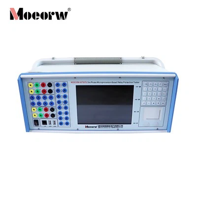
Product Overview
Auto transfer devices ensure uninterrupted power supply for power stations and substations, yet field calibration faces complex wiring, power outage constraints and high error risks. MOEORW-WTB62 is a dedicated embedded tester independently developed for on-site verification of standby power auto-switch equipment. It simulates full substation primary wiring, breakers, transformers and CT/PT logic, reproduces common power faults, outputs analog voltage/current and switch position signals, and automatically records the full action sequence and timing data of auto transfer devices for commissioning and routine maintenance.
Technical Parameters
|
Parameter Category |
Technical Index |
|
Device Power Input |
AC 220V, 50Hz |
|
Rated Output Voltage |
AC 57V / 100V |
|
Max Output Current |
AC 6A |
|
Display Screen |
6.4-inch embedded LCD |
|
Simulatable Circuit Breakers |
10 sets (DL1~DL10) |
|
Simulatable Transformers |
3 sets |
|
Simulatable PT Channels |
12 channels |
|
Simulatable CT Channels |
7 channels |
|
Digital Input Channels |
14 ways |
|
Digital Output Channels |
14 ways |
|
Control Mode |
Timing automatic trigger / Manual button trigger |
|
Report Format |
TXT text file, exportable via USB flash drive |
Main Function Features
Hardware & Design Advantages
1.Real-time embedded operating system with stable signal output, independent analog voltage/current channels without mutual interference
2.Complete analog terminals for PT, CT and breakers, supporting five standard substation primary wiring topologies
3.Dual-color breaker status indicators, real-time graphic display of main wiring topology, voltage and current status
4.Separated public terminals for control and position signals to eliminate wiring logic confusion
Performance Capabilities
1.Freely configurable threshold values for busbar/line presence/absence voltage and loaded/unloaded current
2.Simulate multiple fault conditions: line loss of voltage, transformer failure, manual trip, spontaneous breaker trip
3.Support interlock blocking signal output for transformer fault and manual trip scenarios to verify anti-misoperation logic
4.Two fault trigger modes: preset delay timing control and manual button activation
5.Simulate power recovery after auto-switch action to test reverse switching logic of the device under test
6.Automatic full-process recording of fault cause, each switching action and millisecond-level action time
Practical Application Value
1.Eliminates the need for power cut during on-site auto transfer device commissioning, greatly shortening test duration
2.Visual graphical monitoring reduces manual judgment errors during whole-group testing
3.Standard test report storage and USB export facilitate data archiving and post-failure analysis
4.Customizable initial breaker status and flexible combination of standby power modes to match all mainstream substation operating modes
Application Fields
1.High/medium voltage substation auto transfer device factory inspection and on-site commissioning
2.Power plant auxiliary power standby switching equipment periodic verification
3.Distribution network dual-power automatic switching protection device debugging
4.Power system routine preventive test for busbar sectional auto transfer logic
5.Power equipment third-party testing laboratory auto-switch performance verification
Working Principle
The tester adopts embedded real-time control core to generate standard analog secondary voltage and current signals, and outputs dry contact position signals for simulated breakers.
1.Pre-set normal operating parameters and breaker initial status before test startup
2.Under timing or manual trigger, the system outputs fault voltage/current and corresponding switch state changes
3.Receive trip/close command signals fed back from the tested auto transfer device via digital input channels
4.Dynamically update main wiring graphic status, adjust analog output signals according to breaker action logic
5.Record all action timing and state changes throughout the test cycle and generate standard test logs
Daily Maintenance & Troubleshooting
Daily Maintenance
1.Cut off power supply before wiring or internal inspection
2.Keep terminal jacks clean, remove oxide and dust regularly to avoid poor contact
3.Avoid long-term continuous current output; disconnect current loop wiring after test completion
4.Store in dry, dust-free environment; avoid direct sunlight and humid corrosive atmosphere
5.Regularly check cooling fan operation to prevent overheating damage
Common Fault Troubleshooting
1.No power after power-on: Inspect 5A side panel power fuse, replace burnt fuse with standard 5A tube
2.Abnormal voltage/current output: Recheck software phase/three-phase mode configuration and wiring correspondence
3.Unresponsive breaker signal collection: Verify public terminal wiring of position and trip-close loops
4.Failed report saving/export: Confirm USB flash drive normal connection or local DATA folder storage path
FAQ
Q1: Can this tester work without cutting off substation power supply during field test?
A1: Yes, it simulates secondary analog signals only, no connection to primary live equipment.
Q2: What is the difference between manual trip and spontaneous trip test modes?
A2: Spontaneous trip allows auto transfer action; manual trip outputs blocking signal to lock auto-switch to avoid misoperation.
Q3: How to store and export test records?
A3: Test data auto-saves as TXT files in local DATA folder; plug in USB drive to export all reports.
Q4: Is external input device supported for parameter setting?
A4: The device reserves USB interface, compatible with external USB keyboard and mouse.
Q5: Why auto transfer device fails to act after fault trigger?
A5: Check three items: breaker position wiring polarity, zero-current detection threshold setting, misconnected blocking signal power source.
Hot Tags: comprehensive tester for automatic bus-transfer devices, China comprehensive tester for automatic bus-transfer devices manufacturers, factory, 3 phase relay tester, 6 phase relay tester, Handheld Optical Digital Relay Protection Tester, Six Phase Secondary Current Injection, There Phase Relay Protection Tester, Three Phase Relay Protection Tester Kit