


Capacitance & Tan Delta Tester
Product Introduction
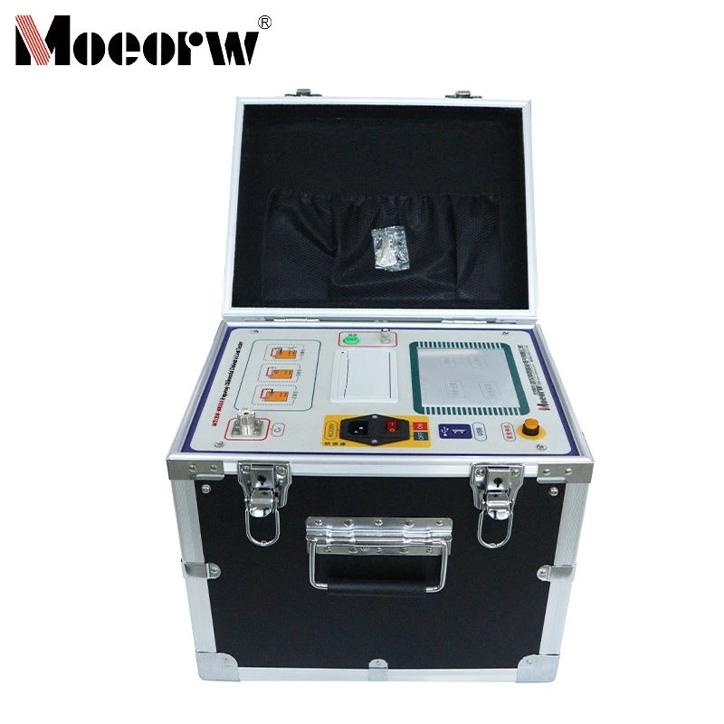
Power plants, substations, and laboratories can make use of the highly accurate MOEORW-W4700A Dielectric Loss Tester. It gauges the capacitance and tangent delta (tan δ) of electrical equipment operating at high voltage. It uses digital notch filter technology to resist interference, supports multiple frequencies and test modes, has large-capacity storage and data export features, includes extensive safety protections, and can be powered by generators. It is compatible with a range of equipment, such as transformers and CVTs, and provides efficient operation with convenience.
Product Parameter (specification)
|
Operating Conditions |
Temperature -10°C to 40°C, Relative Humidity RH < 80% |
|
Interference Suppression Principle |
Frequency Conversion Method |
|
Power Supply |
AC 220V ±10%, Generator Power Supply Permitted |
|
High-Voltage Output |
0.5kV to 10kV, adjustable in 0.1kV increments; Accuracy 2%; Maximum Current 200mA; Capacity 2000VA |
|
Self-excited power supply |
AC 0V to 50V/15A; Single frequency 50.0Hz, 60.0Hz; Automatic dual frequency conversion 45.0Hz/55.0Hz, 47.5Hz/52.5Hz, 55.0Hz/65.0Hz, 57.5Hz/62.5Hz |
|
Resolution |
Dielectric loss tangent tgδ 0.001%, capacitance Cx 0.001pF |
|
Accuracy |
Dielectric loss tangent deviation Δtgδ ±(1.0% of reading + 0.040%); Capacitance deviation ΔCx ±(1.0% of reading + 1.00pF) |
|
Measurement Range |
Dielectric loss tangent tgδ - unlimited; Capacitance Cx - 15 pF < Cx < 300 nF (Cx < 60 nF at 10 kV, Cx < 150 nF at 5 kV, Cx < 300 nF at 1 kV); Cx < 300 nF during CVT testing |
|
Dimensions |
Main unit 350 (L) × 270 (W) × 315 (H) mm; Accessories 350 (L) × 270 (W) × 160 (H) mm |
|
Memory Capacity |
200 sets, supports USB flash drive data storage |
|
Weight |
Main unit 22.55 kg; Accessories case 5.25 kg |
Product feature and application
Extra-large LCD English display
Simple operation:
The instrument features a high-end full-touch LCD screen with an extra-large touch interface. Every process is clearly displayed, requiring no additional professional training for operators. A single tap completes the entire measurement process, making it an ideal intelligent dielectric loss measurement device.
Massive Data Storage
The instrument incorporates a calendar chip and large-capacity memory, storing up to 200 sets of data. Test results are saved chronologically, allowing easy access to historical records and print output.
Scientific and Advanced Data Management
Instrument data can be exported via USB drive for viewing and management on any PC.
Multiple Test Modes
The instrument supports various testing methods including internal high voltage, internal standard, positive connection, reverse connection, and self-excitation.
CVT Measurement Without Disconnecting High-Voltage Leads
Accurate measurement of CVT dielectric loss and capacitance values is possible without disconnecting the high-voltage leads.
CVT reverse-connection shielding method for C0 measurement
The instrument employs the reverse-connection shielding method to measure the dielectric loss and capacitance values of the upper terminal C0 on the CVT.
High-speed sampling signals
The internal inverter and sampling circuits are fully digitally controlled, enabling continuously adjustable output voltage.
Multiple Protections for Safety and Reliability
The instrument incorporates multiple protective measures against input voltage fluctuations, high-voltage current, output short circuits, power supply failures, overvoltage, overcurrent, and temperature extremes, ensuring safe and reliable operation.
It also features a grounding detection function that prevents testing from starting on ungrounded equipment. In the event of accidental connection to 380V power, an alarm function activates to protect the instrument from damage.
Prodection details
Application Scenario Categories: On-site testing at power plants/substations, laboratory precision measurement, emergency testing of generator power supply
Test Object Categories: Capacitive voltage transformers (CVT), voltage transformers (PT), current transformers (CT), high-voltage bushings, power transformers, insulating oil, standard capacitors/standard dielectric loss devices, other high-voltage power equipment (Capacitance Range: 15 pF to 300 nF)
Company Qualifications
Hot Tags: capacitance & tan delta tester, China capacitance & tan delta tester manufacturers, factory, Transformer Capacity And Characteristics Tester, Active Transformer Capacity And Characteristic Tester, transformer capacitance and tan delta tester, High Voltage Cable Dielectric Loss Tester, Transformer Capacity Loss Parameter Tester, Capacitance Tan Delta Tester


