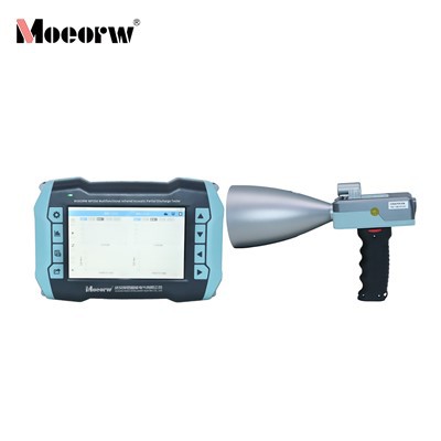
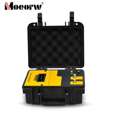
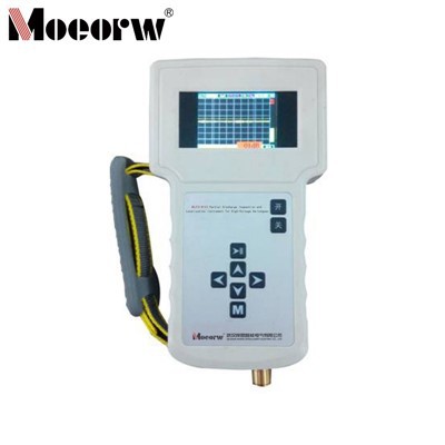
Cable Distributed Partial Discharge Testing System
Product Introduction
Partial discharge detection has long been a primary non-destructive electrical inspection method for cable insulation (especially plastic cables), increasingly regarded as the most effective insulation diagnostic technique for observing and studying insulation aging issues caused by partial discharges.
When partial discharge occurs in a cable, the resulting discharge cavity forms a real impedance. The generated pulses are predominantly unipolar, exhibiting extremely short rise times and narrow pulse widths. As these pulses propagate through the cable, they demonstrate attenuation and scattering characteristics, arriving at the measurement point with increased pulse width and reduced amplitude.
During the end-of-life phase of cables (after 25 years of operation), the failure rate of power cables increases significantly due to the effects of dendritic aging of the cable insulation itself, electrothermal aging, and aging of accessories. Operational experience and research findings both domestically and internationally indicate that the early deterioration of XLPE power cable performance or its service life is largely dependent on the dendritic aging of its insulating medium. Partial discharge measurement is one of the effective methods for quantitatively analyzing the extent of this dendritic deterioration. Example: At the onset of dendrite formation, the cable's partial discharge level is approximately 0.1 pC. When dendrites progress to the critical state of dielectric breakdown, the partial discharge level can reach 1000 pC.
This system enables real-time monitoring of cable partial discharge on a section-by-section or fixed-point basis through high-sensitivity PD sensors installed on high-voltage cable grounding leads, coupled with digital processing units and transmission terminals. Data is transmitted via fiber-optic networks or mobile 4G networks to the monitoring server. Server-side software displays PD data and spectra collected by each detection unit. By configuring detection thresholds, and environmental parameters. When detected partial discharge data exceeds thresholds, the system automatically issues alerts indicating potential insulation defects at the cable node. Relevant measures can then be taken, such as dispatching personnel to conduct on-site fault confirmation tests. Once a fault is confirmed, appropriate actions should be promptly implemented to prevent escalation of the hazard.
Product Parameter (specification)
|
Detection Unit Measurement Parameters |
|
|
Detection Bandwidth |
300KHz to 50MHz |
|
Transmission Impedance |
≥10mV/mA |
|
Test Sensitivity |
Not less than 5pC |
|
Measurement Dynamic Range |
70dB |
|
Gain Range |
-30dB to 20dB |
|
Resolution |
0.1dB |
|
Number of Detection Channels |
3 |
|
Sampling Frequency |
125 MS/s |
|
Sampling Accuracy |
14 bits |
|
Interface Type |
SMA to BNC |
|
Built-in Digital/Analog Filters |
Adjustable bandwidth and type (high-pass, low-pass, band-pass) |
|
Input Impedance |
50 Ω |
|
Dimensions |
295 × 210 × 80 mm |
|
Weight |
2.3 kg |
|
Signal synchronization system |
|
|
Input voltage range |
AC 20–250V |
|
Synchronization modes |
Sensor internal sync, system internal sync, system voltage sync, external current sync, and other synchronization methods. |
|
Time base synchronization accuracy |
≤2ns |
|
Frequency range |
20–300Hz |
|
Phase accuracy |
0.1° |
|
Input impedance |
10M |
|
Dimensions |
295*210*80 mm |
|
Weight |
2.3 kg |
|
Communication Modes |
|
|
Supports wired and wireless modes |
|
|
Environmental Conditions |
|
|
Ambient temperature |
-15°C to 50°C |
|
Relative humidity |
≤90% |
|
Power Supply |
DC 12.6V rechargeable battery Spectrum Display |
♦ The system operates on the Windows platform, providing real-time display of measurements across all channels. Multiple observation windows are freely selectable, including phase line, sine, flight, 2D, 3D, elliptical window, trend, and discharge analysis. Detailed measurement, observation, and analysis of partial discharge pulses from single-frequency or multi-frequency test voltages can be performed statically or dynamically. It separates and classifies different discharge or interference signals to analyze characteristic parameters for each signal category, including discharge quantity, signal amplitude, phase, and discharge repetition rate. It features time-domain and frequency-domain analysis capabilities, allowing users to perform time-domain or frequency-domain analysis at any point on the spectrum diagram.
Product feature and application
• Distributed Layout with Strong Scalability
The networked deployment of monitoring terminals enables the entire system to support simultaneous detection by up to 100 monitoring units. When adding or removing terminals from the existing layout, the system automatically identifies and configures them without requiring additional setup.
• Real-Time Monitoring
The system records real-time data from each monitoring node, with flexible configuration of monitoring cycles.
• Edge Computing
Aligns with current IoT terminal design principles: computation at the edge, on-site data processing, remote analysis and judgment, with data replay and traceability mechanisms.
• Flexible Access and Inspection
Monitoring units are also suitable for line inspection scenarios. Simply bring a computer equipped with partial discharge analysis software to use with the terminals.
• Multiple Connection Methods
Supports fiber optic network connections and wireless 4G network connections between monitoring units, ensuring stable transmission.
• Multiple Synchronization Methods
Supports sensor-level synchronization, system-level synchronization, and external synchronization for high-voltage testing, accommodating diverse testing scenarios.
• High Sensitivity
Detects discharge signals as low as 5 pC.
• Shock Resistance
Withstands 600kV flashover impacts without terminal damage or data loss.
• Interference Resistance
Features time-domain and frequency-domain signal analysis technology to effectively separate interference signals from partial discharge signals, while preventing interference at the instrument's power supply end.
Prodection details
1. Live-line testing of 10–1000 kV power cables without power interruption
2. Partial discharge monitoring of cable bodies and accessories (primarily cable terminations)
3. Diagnosis of cable insulation aging (including dendritic deterioration)
4. Cable line patrol inspections and long-term online monitoring
5. Partial discharge detection and localization during high-voltage testing scenarios (e.g., withstand voltage tests)
Company Qualifications
Hot Tags: cable partial discharge tester, China cable partial discharge tester manufacturers, factory, GIS Partial Discharge Tester, Partial Discharge Tester For High Voltage Switchgear, ultrasonic partial discharge tester, 4 Channel Portable Partial Discharge Tester, Cable Partial Discharge Tester, Transformer Partial Discharge Tester