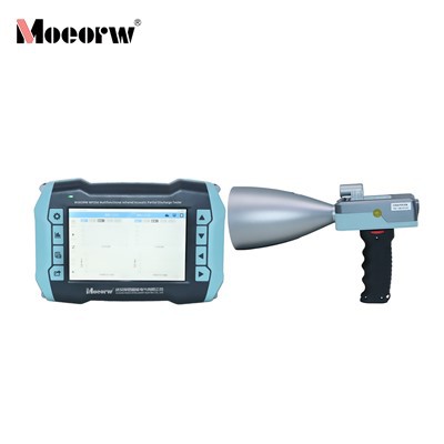
4-Channel Portable Partial Discharge Tester
Product Introduction
This instrument employs high-frequency detection technology to measure partial discharges. It integrates computer technology, ultrasonic technology, ultra-high frequency technology, transient earth-wave sampling technology, analog electronics, high-speed signal acquisition technology, and advanced digital signal processing technology. Developed on a Linux operating system platform, it provides two-dimensional and three-dimensional partial discharge spectra, amplitude-phase spectrum waveforms, and partial discharge signal quantification values. Through detailed observation and analysis of partial discharge pulse waveforms-either statically or dynamically over single or multiple cycles-it enables thorough evaluation of partial discharge characteristics. and phase spectrum waveforms, along with quantified discharge signal values. By conducting detailed observation and analysis of partial discharge pulse waveforms-either statically or dynamically across single or multiple cycles-it effectively evaluates partial discharge conditions in electrical equipment. Suitable for routine inspections of insulation performance in high-voltage cables, power transformers, and other electrical equipment, it features high sensitivity and strong adaptability. This instrument effectively detects related insulation defects, making it an ideal tool for condition monitoring during live operation of power equipment.
Product Parameter (specification)
|
2.1 Non-contact Ultrasonic Sensor (AA) |
|
|
Sensor Center Frequency |
40KHz±1KHz |
|
Dynamic Measurement Range |
60dB |
|
Resolution |
0.1dB |
|
Linearity Error |
<±20% |
|
Sensor Form |
Flexible Form/Focusing Element Form |
|
2.2 Contact Ultrasonic Sensor (AE) |
|
|
Detection Bandwidth |
20KHz~80KHz (SF6 Gas-Insulated Power Equipment) |
| 80KHz~200KHz (Oil-Filled Power Equipment) | |
|
Dynamic measurement range |
60dB |
|
Resolution |
0.1dB |
|
Linearity error |
<±20% |
|
2.3 Transient Earth Voltage Sensor (TEV) |
|
|
Detection frequency band |
3MHz~100MHz |
|
Measurement range |
0~60dBmV |
|
Resolution |
0.1dB |
|
Linearity error |
<±20% |
|
2.4 Ultra-High Frequency Sensor (UHF) |
|
|
Detection Bandwidth |
300MHz~1500MHz |
|
Measurement Range |
-70dBm~-10dBm |
|
Sensor Mean Effective Height |
≥10mm |
|
Resolution |
0.1dBm |
|
2.5 High-Frequency Sensor (HF) |
|
|
Detection Bandwidth |
0.3MHz to 30MHz |
|
Measurement Range |
0 to 70dB |
|
Gain |
-30 to 20dB |
|
Resolution |
0.1dB |
|
Transmission Impedance |
≥10mV/mA |
|
Input Impedance |
50Ω |
|
2.6 System Specifications |
|
|
Operating Environment |
Temperature -20°C to 50°C, Humidity 0% to 85% |
|
Display |
High-definition 5.6-inch TFT color LCD, Resolution 480×640 |
|
Main Unit Dimensions |
230×170×48 mm |
|
Main Unit Weight |
1.35 kg |
|
Battery Life |
Approximately 6 hours |
Product feature and application
1) Enables rapid on-site detection of partial discharge conditions in high-voltage electrical equipment, particularly high-voltage cables. Features user-friendly operation, compact size, lightweight design, and portability.
2) The partial discharge detection sensor incorporates advanced RF signal processing, high-frequency signal processing, and weak signal processing technologies. Utilizes high-precision AD conversion and high-speed digital signal processing chips for digital signal processing, delivering excellent anti-interference performance and measurement accuracy.
3) Combines ultrasonic, transient earth wave, high-frequency, and ultra-high-frequency detection methods for comprehensive partial discharge signal analysis.
4) Features a built-in non-contact ultrasonic sensor and supports configurable external surface-mount ultrasonic sensors.
5) Provides multiple analysis windows including phase line, PRPD, and PRPS for interpreting partial discharge test data.
6) Supports data storage, viewing, and deletion functions.
7) Supports waveform data recording.
8) Supports multi-level threshold settings for warnings and alarms, providing intuitive visual alerts through color-coded amplitude indicators.
9) Powered by a high-capacity lithium battery, enabling 6–8 hours of continuous operation per charge.
10) Utilizes Linux as the embedded operating system, facilitating future functional expansion and integration with IoT technologies.
Prodection details
When applied to the live operation monitoring of most electrical equipment
Company Qualifications
Hot Tags: 4-channel portable partial discharge tester, China 4-channel portable partial discharge tester manufacturers, factory, GIS Partial Discharge Tester, Partial Discharge Tester For High Voltage Switchgear, ultrasonic partial discharge tester, 4 Channel Portable Partial Discharge Tester, Cable Partial Discharge Tester, Transformer Partial Discharge Tester