


Simulation 3-Channel Partial Discharge Detector
Product Introduction
This instrument incorporates advanced theories from current domestic and international research in partial discharge analyzers, adheres to International Electrotechnical Commission (IEC) standards, employs sophisticated circuitry, and utilizes cutting-edge technology. Refined through extensive field testing by users worldwide, it features enhanced design, greater operational convenience, and improved reliability.
Product Parameter (specification)
1. Number of measurement channels: 3 channels (standard)
2. The capacitance range of the testable samples is 6pF~250µF.
3. Allowable current for detection sensitivity (see Table 1):
Table 1. Detection sensitivity and allowable current value of input unit.
|
Input form Yuan serial number |
Tuning capacitor range |
Sensitivity (PC) (Unbalanced circuit) |
Permissible current RMS value |
|
|
Unbalanced circuit |
Balanced circuit |
|||
|
1 |
0~25~100PF |
0.02 |
30 mA |
0.25A |
|
2 |
25 ~ 100 ~ 400PF |
0.04 |
50mA |
0.5A |
|
3 |
100 ~ 400 ~ 1500PF |
0.06 |
120mA |
1A |
|
4 |
400 ~ 1500 ~ 6000PF |
0.1 |
0.25A |
2A |
|
5 |
1500 ~ 6000 ~ 25000PF |
0.2 |
0.5A |
4A |
|
6 |
0.006 ~ 0.025 ~ 0.1 μF |
0.3 |
1A |
8A |
|
7 |
0.025 ~ 0.1 ~ 0.4 μF |
0.5 |
2A |
15A |
|
8 |
0.1 ~ 0.4 ~ 1.5 μF |
1 |
4A |
30A |
|
9 |
0.4 ~ 1.5 ~ 6.0 μF |
1.5 |
8A |
60A |
|
10 |
1.5 ~ 6.0 ~ 25 μF |
2.5 |
15A |
120A |
|
11 |
6.0 ~ 25 ~ 60 μF |
5 |
25A |
200A |
|
12 |
25 ~ 60 ~ 250 μF |
10 |
50A |
300A |
|
7R |
resistance |
0.5 |
2A |
15A |
|
4. Elliptical scan time base |
|
|
(1) Internal and external triggering functions can realize synchronous triggering of frequency 50 (internal) and external high-frequency test power supply. |
|
|
(2) Rotation |
Rotate in increments of 30° to adjust the viewing angle. |
|
(3) The high-frequency time base ellipse can be adjusted to the normal size according to the input voltage (10~250V) and its power intake is < 1 volt-ampere. |
|
|
5. Display Unit |
|
|
(1) It adopts a 5.6-inch rectangular LCD display, which displays colors clearly. |
|
|
(2) Working method |
Ellipse and line display, continuous and pause measurement. |
|
6. Amplifier |
|
|
(1) 3 dB low-frequency end frequency f L |
10, 20, 40KH Z can be selected. |
|
(2) 3 dB high-frequency end frequency f H |
80, 200, 300KH Z can be selected. |
|
(3) Gain adjustment |
coarse adjustment has 6 levels with a gain difference of 20±1 dB between levels , and fine adjustment range > 20 dB . |
|
(4) Positive and negative impulse response asymmetry |
<1dB . |
|
7. Time windo |
|
|
(1) Window width |
adjustable, 15° at 50Hz 150°. |
|
(2) Window position |
Each window can be rotated 0°~ 170°. |
|
(3) The two time windows can be opened separately or simultaneously. |
|
|
8. Pulse Peak Value Table |
|
|
(1) Digital display |
Displayed using a 3.5-digit LED digital meter |
|
0-100 Error |
±3% (based on full scale). |
|
9. Test voltmeter |
|
|
(1) Range 200KV (a resistor or capacitor voltage divider is required). |
|
|
(2) Display |
3.5-digit digital voltmeter. |
|
(3) Error |
±3%. |
|
10. Zero-standard system |
|
|
(1) The polarity of the zero mark of the internal zero mark generator can be changed and it can be rotated 0 to 180° so that the true zero mark generated by the voltage resistor R is in the same polarity. |
|
|
(2) The zero mark is consistent with all elliptical scan frequencies. |
|
|
11. Structure |
|
|
(1) Dimensions |
Width 430 × Height 190 × Depth 480 mm 3 |
|
(2) Weight |
Approximately 12kg . |
Product feature and application
## I. Core Functional Advantages
1. **Multi-Channel Measurement Capability**: Standard configuration includes 3 measurement channels, supporting simultaneous multi-channel partial discharge testing. Suitable for scenarios such as dry-type transformer induced PD (3 channels) and oil-filled transformer induced PD (3 or 6 channels). Eliminates the need for multiple instruments, providing an efficient solution for multi-channel testing.
2. **Broad Adaptability Range**: Covers test specimen capacitance from 6 pF to 250 µF. Equipped with a 12-step tunable capacitance input unit and resistive input unit, it meets testing requirements for various high-voltage electrical products, ensuring wide applicability.
3. **High-Precision Measurement Performance**: Features low sensitivity of 0.02 pC for unbalanced circuits and excellent sensitivity for balanced circuits. The amplification system offers a wide dynamic range with pulse response asymmetry <1 dB, ensuring accurate and stable discharge readings for both small and large signals. Both the pulse peak meter and test voltage meter provide 3½-digit digital displays with an error of only ±3%, guaranteeing reliable measurement accuracy.
## II. Operational and Display Convenience
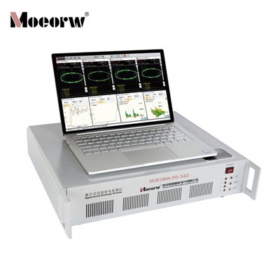
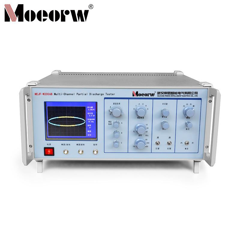
1. **Clear Visual Display**: Features a 5.6-inch rectangular color LCD supporting elliptical and linear display modes, intuitively presenting partial discharge patterns, discharge quantities, voltage values, and other data. External VGA monitors can be connected to accommodate diverse observation needs.
2. **Flexible Measurement Modes**: Supports continuous or single-shot measurements. Elliptical scan time base rotates in 30° increments for adjustable viewing angles. Internal/external triggering enables synchronization with 50Hz power frequency or external high-frequency test sources, adapting to diverse test conditions.
3. **Convenient Adjustment Functions**: The amplifier offers 6 coarse adjustment steps (20±1dB gain difference per step) and >20dB fine adjustment range. Selectable multi-band combinations include 10/20/40kHz (low-frequency end) and 80/200/300kHz (high-frequency end). Adjustable time window width (15°–150°) and position (0°–170°), supporting single-window or dual-window operation to effectively avoid fixed-phase interference.
## III. Structural and Practical Design
1. **Compact Portable Design**: Dimensions of only 430×190×480mm³, weighing approximately 12kg, facilitates on-site portability and mobile testing, suitable for both laboratory R&D and field equipment inspection scenarios.
2. **Reliable and Stable Operation**: Features pluggable printed circuit boards for easy maintenance. The built-in zero marking system allows polarity reversal and 0°–180° rotation of the zero mark, perfectly synchronized with elliptical scanning frequency to ensure testing accuracy. Instrument power consumption <1 VA, delivering low energy usage and high stability.
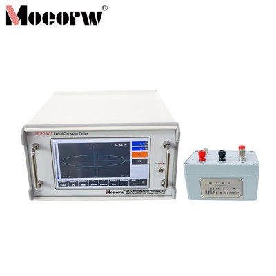
3. **Compatible with Standardized Accessories**: Compatible with JZF-type calibration pulse generators, supporting multiple test specimen connection methods including parallel, series, balanced, and bridge configurations. Designed per IEC standards, it suits diverse applications across power utilities, manufacturing plants, and research institutions.
## IV. Enhanced Interference Resistance and Adaptability
1. **Multi-Layer Interference Suppression**: Effectively mitigates power network, grounding system, and electromagnetic radiation interference through shielded grounding, high-voltage filters, time-window filtering, and narrow-band amplifiers, ensuring testing precision in complex environments.
2. **Wide Voltage and Frequency Adaptability**: The test voltage meter ranges up to 200kV (customizable for higher voltages), with high-frequency time base ellipticity adjustable from 10 to 250V input voltage. Supports both 50Hz power frequency and high-frequency partial discharge testing above 50Hz, accommodating diverse test power requirements.
3. **Precise Discharge Type Identification**: Equipped with comprehensive discharge waveform analysis capabilities, it assists in distinguishing multiple discharge types and interference signals-including internal bubbles, floating potentials, corona discharges, and poor contacts-providing reliable basis for product quality diagnosis and equipment fault determination.
Prodection details
1. Power Sector: On-site partial discharge detection and condition assessment of equipment
2. Manufacturing Plants: Quality inspection and factory acceptance testing of high-voltage electrical products
3. Research Institutions: R&D and performance testing of novel high-voltage electrical products
4. Related Industries: Multi-channel synchronous testing scenarios such as dry-type/oil-immersed transformer induction partial discharge testing
Company Qualifications
Hot Tags: simulation 3-channel partial discharge detector, China simulation 3-channel partial discharge detector manufacturers, factory, Multi channel Digital Partial Discharge Comprehensive Analyzer, Partial Discharge Tester, Partial Discharge Online Test, Simulation 2 Channel Partial Discharge Detector, partial discharge test equipment, Digital Partial Discharge Comprehensive Analyzer