Digital Partial Discharge Comprehensive Analyzer
Product Introduction
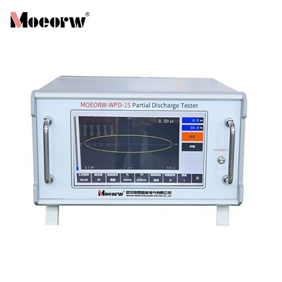
The MEJFD-W1S Partial Discharge Tester is a new digital partial discharge testing instrument developed by our company. It retains the strengths of previous models while reducing its size and further optimizing performance. The traditional oscilloscope tube and physical knob operation has been replaced with a 10.1-inch touchscreen, enhancing functionality, ease of use, and reliability.
This instrument utilizes a 32-bit high-performance microcontroller circuit combined with touchscreen operation. This not only extends operational lifespan but also provides the following features: one-touch automatic calibration; configurable high-voltage test voltage division ratio; serial port communication for uploading test data. This instrument features high detection sensitivity, broad applicability across test specimens, a wide dynamic range in its amplification system, multiple frequency band combinations (nine types), and strong anti-interference capabilities. When used in conjunction with a calibration pulse generator and input unit, it serves as a practical partial discharge testing instrument widely adopted by power utilities, manufacturers, and research institutions.
Product Parameter (specification)
- The equivalent capacitance range of the testable samples is 6pF to 250µF.
- Measurement range: 0.1 pC - 10000 nC
- Number of channels: Single channel
- Detection sensitivity and allowable current (see Table 1)
|
Input unit Serial Number |
Tuning capacitor range |
Sensitivity (pC) (Unbalanced circuit) |
Permissible current RMS value |
|
|
Unbalanced circuit |
Balanced circuit |
|||
|
1 |
0~25~100pF |
0.02 |
30mA |
0.25A |
|
2 |
25~100~400pF |
0.04 |
50mA |
0.5A |
|
3 |
100~400~1500pF |
0.06 |
120mA |
1A |
|
4 |
400~1500~6000pF |
0.1 |
0.25A |
2A |
|
5 |
1500~6000~25000pF |
0.2 |
0.5A |
4A |
|
6 |
0.006~0.025~0.1μF |
0.3 |
1A |
8A |
|
7 |
0.025~0.1~0.4μF |
0.5 |
2A |
15A |
|
8 |
0.1~0.4~1.5μF |
1 |
4A |
30A |
|
9 |
0.4~1.5~6.0μF |
1.5 |
8A |
60A |
|
10 |
1.5~6.0~25μF |
2.5 |
15A |
120A |
|
11 |
6.0~25~60μF |
5 |
25A |
200A |
|
12 |
25~60~250μF |
10 |
50A |
300A |
|
7R |
resistance |
0.5 |
2A |
15A |
Table 1. Detection Sensitivity and Allowable Current Value of Input Unit
|
5. Elliptical Scan Time Base |
|
|
(1) Frequency |
50/60, 100, 150, 200, 400Hz |
|
(2) Rotation |
In increments of 30°, it can rotate up to 120°. |
|
(3) Working method |
Ellipse - Sine wave - Straight line |
|
6. Display Unit |
It uses a 10.1-inch capacitive touchscreen. |
|
7. Amplifier |
|
|
(1) 3dB low-frequency end frequency fL |
10, 20, 40kHz (selectable) |
|
(2) 3dB high-frequency end frequency fH |
80, 200, 300kHz selectable |
|
(3) Gain adjustment |
coarse adjustment has 6 levels with a gain difference of 20±1dB between levels; fine adjustment range is >20dB. |
|
(4) Asymmetry of positive and negative impulse response |
<1dB |
|
8. Time window |
|
|
(1) Window width |
Adjustable, 5°~170° at 50Hz |
|
(2) Window position |
Each window can be rotated from 0° to 170°. |
|
(3) The two time windows can be opened separately or simultaneously. |
|
|
9. Pulse peak display |
|
|
Touchscreen display |
shows 1 decimal place (greater than or equal to 10 pC) or 2 decimal places (less than 10 pC), with an error of ±3% (full scale). |
|
10. Test voltage display |
|
|
(1) Range |
150kV |
|
(2) Input impedance |
>1MΩ |
|
(3) Display |
Touch screen display, displaying to 1 decimal place. |
|
(4) Error |
±1% |
|
11. Test frequency display |
|
|
Error |
less than ±1% |
|
12. Zero-standard system |
|
|
The zero mark is consistent with all elliptical scan frequencies. |
|
|
13. Structure |
|
|
(1) Dimensions |
370mm (width), 460mm (depth), 215mm (height) |
|
(2) Weight |
Approximately 12.5 kg |
Product feature and application
I. Outstanding Operational Convenience
1. Upgraded Interaction: Features a 10.1-inch capacitive touchscreen, replacing traditional cathode ray tube displays with physical knobs. The intuitive interface and flexible operation significantly reduce learning curves while extending operational lifespan.
2. Intelligent Convenience Features: Supports one-touch automatic calibration, eliminating complex manual calculations. After injecting a known charge via the JZF-type calibration pulse generator, the instrument automatically calibrates and directly displays the discharge quantity of the test specimen. Equipped with serial communication functionality, it facilitates seamless upload of test data to other devices for efficient archiving and analysis.
3. Flexible Parameter Adjustment: The high-voltage test voltage division ratio is freely configurable. Key parameters such as elliptical scan time base, amplifier bandwidth, gain, and time window are all adjustable via one-touch controls on the touchscreen, ensuring efficient operation.
II. Outstanding Performance Metrics
1. High Detection Sensitivity: For test specimens with varying equivalent capacitance, the unbalanced circuit sensitivity reaches as low as 0.02 pC (corresponding to a tuning capacitance range of 0–25–100 pF). The balanced circuit sensitivity adapts synchronously, enabling precise capture of faint partial discharge signals.
2. Extensive Measurement Range: Covers test specimens with equivalent capacitance from 6 pF to 250 µF and discharge measurement from 0.1 pC to 10,000 nC, meeting testing requirements for diverse power equipment and components.
3. Strong Anti-Interference Capability: Equipped with nine frequency band combinations, the amplifier's 3dB low-frequency end (10, 20, 40kHz) and high-frequency end (80, 200, 300kHz) are freely selectable. Combined with the time window function (window width adjustable from 5° to 170°, dual windows can be activated independently or simultaneously), it effectively avoids fixed-phase interference. Supports elliptical scan time base rotation (in 30° increments, up to 120° rotation) to further optimize interference resistance.
4. Reliable Measurement Accuracy: Pulse peak display error is only ±3% (at full scale), test voltage display error is ±1%, and test frequency display error is less than ±1%. The zero calibration system remains consistent across all elliptical scan frequencies, ensuring accurate and reliable test data.
III. Extensive Functional Adaptability
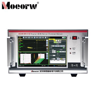
1. Rich Scanning and Display Capabilities: Elliptical scan time base supports multiple frequencies (50/60, 100, 150, 200, 400Hz), with operating modes covering elliptical, sinusoidal, and linear waveforms to accommodate diverse waveform observation requirements across testing scenarios; The touchscreen clearly displays key parameters including PD waveforms, PD values, test voltage, and test frequency. Discharge quantity readings automatically switch between 1-digit or 2-digit decimal displays based on magnitude for enhanced readability.
2. High Input Unit Adaptability: Equipped with input units featuring 12 tunable capacitance ranges and one resistive input unit, accommodating current rms values from 30mA to 50A (unbalanced circuits) and 0.25A to 300A (balanced circuits). This flexibility enables testing of specimens with varying capacitance and current ratings.
3. Versatile Application Scenarios: When used with calibration pulse generators and input units, it is widely applicable in power utilities, manufacturing plants, and research institutions. It meets partial discharge testing requirements for transformers, capacitors, cables, and other power equipment, supporting tests at 50Hz and frequencies above 50Hz.
IV. Practical Structural Design
1. Compact and Portable: Features a desktop standard chassis with dimensions of 370mm (W) × 460mm (D) × 215mm (H) and weighs approximately 12.5kg. Its smaller footprint compared to traditional instruments facilitates mobility and on-site testing.
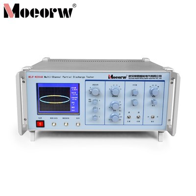
2. Intuitive Interface Layout: The front panel houses key components including a touchscreen, power switch, and partial discharge input terminals. The rear panel features grounding bolts, an RS232 port, and external power supply inputs, ensuring convenient wiring, reliable grounding, and enhanced testing safety.
Prodection details
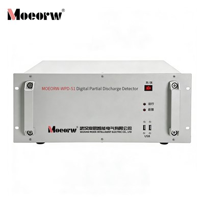
This equipment is used for partial discharge detection and testing of power equipment, including transformers, capacitors, and cables, and is appropriate for manufacturers, research institutions, and power utilities.
Company Qualifications
Hot Tags: digital partial discharge comprehensive analyzer, China digital partial discharge comprehensive analyzer manufacturers, factory, Multi channel Digital Partial Discharge Comprehensive Analyzer, Partial Discharge Tester, Partial Discharge Online Test, Simulation 2 Channel Partial Discharge Detector, partial discharge test equipment, Digital Partial Discharge Comprehensive Analyzer