Multi-channel Digital Partial Discharge Comprehensive Analyzer
Product Introduction
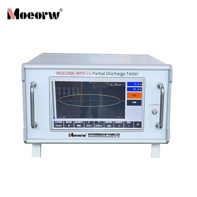
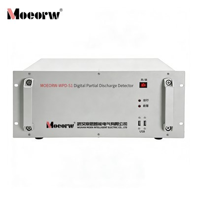
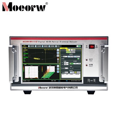
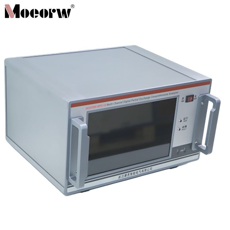
The MOEORW-PS12 Multi-Channel Digital Partial Discharge Comprehensive Analyzer (also referred to as PD detector, digital PD tester, or PD measuring instrument) features an integrated design suitable for quantitative partial discharge testing of high-voltage electrical equipment in both laboratory and field environments. This PD test system enables insulation condition assessment of transformers, instrument transformers, power cables, bushings, capacitors, GIS, generators, switchgear, and other high-voltage apparatus, assisting maintenance personnel in identifying internal defects before they lead to unplanned outages.
The system strictly complies with IEC 60270 and GB/T 7354-2018 standards, ensuring that test results are fully compliant and can be directly used in type test reports, factory quality inspection reports, and acceptance handover documentation.
Product Parameter (specification)
| Parameter | Specification | Direct Customer Value |
|---|---|---|
| Measurement Sensitivity | <1pC (standard circuit) / <0.01pC (small capacitance circuit) | Captures weak discharge signals generated by early-stage insulation degradation. Higher sensitivity provides a wider early warning window, allowing more time for maintenance decision-making. |
| Sampling Rate & Resolution | 100MHz / 14bit | PD pulse widths are typically in the nanosecond range; 100MHz sampling ensures waveform fidelity; 14-bit vertical resolution prevents weak signals from being masked by quantization noise. |
| Analog Filter Bandwidth | Lower limit selectable: 10/20/40/60/80kHz; Upper limit selectable: 100/200/300/400/500kHz/1MHz | Fixed bandwidth tends to filter out valid signals along with interference in field environments with abundant electromagnetic noise. Multiple combinations allow "tuning" the optimal signal-to-noise window for different interference scenarios. |
| Gain Adjustment | 6 ranges from 60dB to -40dB, automatic/manual switching | Covers signals from pC-level weak discharges to nC-level strong discharges without changing peripheral modules, preventing signal saturation or loss of weak signals. |
| Linearity Error | <±3% | Ensures good linearity of readings across different discharge amplitudes, facilitating longitudinal comparison of historical trend data for the same equipment. |
| Test Object Capacitance Range | 6pF ~ 250μF | Covers a wide range from small capacitance of bushings to large capacitance of long cables. A single digital PD tester can handle various test objects, reducing duplicate equipment purchases. |
| Synchronization Method | Power synchronization / external voltage input synchronization, automatic switching | When power frequency is unavailable on-site, the phase reference can be directly extracted from external voltage signals, ensuring phase-resolved patterns remain accurate at all times. |
| Synchronization Accuracy | <1° | High-precision synchronization is the foundation for effective PRPD/PRPS patterns-phase deviation exceeding 5° may misidentify actual discharges as interference or vice versa. |
Measurement Functions and Data Analysis
This PD measurement system provides three interrelated views at the software level, covering requirements from rapid screening to in-depth diagnosis:
PRPD Pattern (Phase-Resolved Partial Discharge Pattern) - Displays the three-dimensional relationship among discharge magnitude (q), power frequency phase (φ, 0~360°), and discharge count (n). This is the most widely used PD analysis pattern in the industry, used to identify discharge types (internal discharge, surface discharge, corona, etc.).
PRPS Pattern (Phase-Resolved Pulse Sequence Pattern) - Displays each discharge pulse with its phase identifier sequentially in chronological order. This mode preserves the most complete raw data and is particularly suitable for analyzing intermittent discharges or the evolution of discharge behavior caused by changing operating conditions.
Time-Domain Waveform Window - Displays PD pulse waveforms within the current power frequency cycle in real time, with baseline modes (straight line/ellipse/sine wave, three display options), used to observe the specific morphology and time-domain characteristics of discharge pulses.
All three are displayed simultaneously, cross-validating each other, significantly reducing the probability of misjudgment.
Calibration System and Traceability
The output data of any partial discharge detector must be calibrated before it possesses legal validity and engineering reference value. This system provides complete closed-loop management in the calibration process:
PD Magnitude Calibration - Uses the accompanying calibration pulse generator (output charge selectable: 10/50/100/500 pC; frequency adjustable from 50~1000Hz) to inject a known charge quantity into the test circuit without applying high voltage to the test object. After calibration is completed, the system automatically saves the calibration coefficient for the current channel and forces recalibration when the filter bandwidth is switched, avoiding the common operational pitfall of "calibrated but readings distorted due to bandwidth changes." The calibration records (bandwidth, calibration value, time) for each channel can be queried directly in the interface.
Voltage Calibration - Provides three methods to flexibly adapt to different test scenarios: 1. Direct calibration: input the actual voltage value against an independent high-voltage divider reading, and the system automatically fits the ratio coefficient; 2. Manual setting: directly enter the known divider ratio (V/kV); 3. Smart setting: input the coupling capacitance and low-voltage arm capacitance values, and the system calculates automatically.
After calibration, the interface uses green/yellow dual-color status indicators to visually indicate whether the current channel is validly calibrated, preventing operators from omitting the calibration step.
Calibration Data Storage - The configuration file from each calibration can be saved independently. When testing the same test object again, historical calibration parameters can be loaded with one click, eliminating repetitive operations and improving batch testing efficiency. This feature is particularly valued by B-end customers in factory test scenarios.
Interference Suppression Capability
The core challenge in on-site PD detection is often not insufficient instrument sensitivity, but the various interference signals present in the environment. This digital PD tester integrates three anti-interference strategies, each targeting different types of noise sources:
| Interference Type | Typical Sources | Suppression Method of This System |
|---|---|---|
| Fixed-Phase Interference | Corona from adjacent high-voltage equipment, switching power supply harmonics | Phase Window Blanking - Electronically masks signals within specific phase intervals, supports single or multiple windows, easy to operate. |
| Non-Fixed-Phase Interference | Motor start/stop, welding, variable frequency drives, wireless communication | Pulse Smoothing - Utilizes the phase-repeatability characteristic of PD signals in each power frequency cycle, attenuating random interference through moving average. |
| Phase-Overlapping Interference | Interference and discharge occur in the same phase interval | Time Window Method - Adjusts the start position and width of the detection window, limiting display and measurement range to a specific phase interval, reading the maximum discharge within the window while blanking signals outside. |
These three methods can be used independently or in combination to cope with complex field environments. The interference suppression status is clearly indicated at the top of the waveform window, allowing operators to confirm the currently active suppression strategy at any time.
Data Management and Traceability
For power equipment manufacturers and maintenance organizations, the PD measurement system not only performs detection functions but also serves as a data acquisition terminal for the quality traceability system. This system provides the following data-level support:
Test Management System - By filling in test object information (equipment ID, model, test location, operator, etc.) in the "Test Management" module, independent test files can be created. All waveform screenshots, PRPD/PRPS patterns, measurement parameters, and calibration records are automatically consolidated under the corresponding file, preventing data fragmentation.
Dual-Format Storage - Upon clicking the save button, the system simultaneously generates image files (pattern and waveform screenshots) and .ini data files. Images are used for report illustrations and archiving, while data files facilitate subsequent secondary analysis or import into professional diagnostic software.
Append Test Function - For already completed test files, new measurement data can be appended without overwriting the original data, making it suitable for long-term tracking of discharge trends of the same equipment across different test cycles.
Local storage capacity ≥8GB supports the accumulation of test data for consecutive months. For data transfer, files can be directly exported via USB interface or interfaced with host computer systems through the RS232 port.
Application Scenarios
This PD detector is widely used in insulation testing of the following high-voltage electrical equipment:
Transformers (Power Transformers / Distribution Transformers)
Uses frequency-multiplied power (150~250Hz) or power frequency supply, single-phase or three-phase excitation. The parallel connection test circuit is recommended, with the measuring impedance connected in series on the grounded side of the coupling capacitor, and the signal taken from the transformer bushing tap. Measurement of partial discharge inception voltage and extinction voltage helps determine the aging condition of the transformer's main insulation and longitudinal insulation.
Voltage Transformers / Current Transformers
Suitable for both oil-immersed and epoxy-resin cast instrument transformers. For oil-immersed products, the #2 measuring impedance is recommended; for epoxy cast types, the #3 measuring impedance is recommended. During field testing, when high-voltage excitation is not feasible due to power supply limitations, the secondary winding self-excitation method (low-voltage side energization) can be used, with stray capacitance replacing the coupling capacitor, still yielding effective results. The balanced connection method can be used for anti-interference measurements under strong external interference.
Power Cables (Medium Voltage / High Voltage)
For long cables (≥500m), pulse propagation and reflection effects in the cable must be considered. Installing terminal matching impedance at the far end effectively avoids misjudgment caused by reflected pulse superposition. Two circuit configurations-measuring impedance in series with the cable or in series with the coupling capacitor-are recommended, selected based on cable length and grounding conditions.
GIS (Gas-Insulated Switchgear)
Performed in accordance with the DL/T 617 standard. During the test, the external power frequency voltage is first raised to the pre-stress voltage (power frequency withstand value) and held for 1 minute, then reduced to the specified PD measurement voltage for detection, while simultaneously recording the discharge extinction voltage. The coupling capacitor may be built-in or external, with the measuring impedance connected in series on the grounded side.
Generators (Stator Coils / Complete Windings)
For individual bars or coils, the parallel or series basic test circuits may be used, with the coupling device connected either on the grounded side of the coupling capacitor or on the grounded side of the test object. For complete windings, the PD coupling unit should be connected as close as possible to the winding end, utilizing the winding's own damping effect to suppress conducted interference from the power supply side. The stator core must be reliably grounded, and measurements performed at the high-voltage end of the winding to obtain authentic PD information.
High-Voltage Bushings
During testing, the lower portion of the bushing must be immersed in qualified oil and allowed to stand for 48 hours before testing. Stray capacitance replaces the coupling capacitor, with the capacitance tap signal connected to the measuring impedance input. Wall bushings and other types of bushings do not require oil immersion and use the same connection method.
Coupling Capacitors and Capacitive Voltage Transformers
For those with a tap terminal, the measuring impedance is connected in series between the tap and the bottom flange, with the bottom flange directly grounded. For those without a tap terminal, the entire test object is insulated from ground, and the measuring impedance is connected in series between the bottom flange and ground.
Measuring Impedance Selection Guide
The measuring impedance (also referred to as the input unit) is the key adaptation component between the PD test system and the high-voltage circuit. The capacitance of different test objects varies significantly-improper selection directly leads to reduced sensitivity or even failure to detect valid signals.
The tuning capacitance calculation formula is: Ct = (Ck × Ca) / (Ck + Ca)
Where Ck is the coupling capacitance and Ca is the test object capacitance. Selection principle: ensure the actual tuning capacitance falls near the "center value" of the selected impedance model.
| Impedance Model | Tuning Capacitance Range | Maximum Current (Unbalanced/Balanced) | Recommended Application |
|---|---|---|---|
| #1 | 6~100pF | 30mA / 0.25A | Small capacitance objects, e.g., high-voltage bushings |
| #2 | 25~400pF | 60mA / 0.5A | Oil-immersed instrument transformers |
| #3 | 100~1500pF | 120mA / 1A | Epoxy cast instrument transformers |
| #4 | 400~6000pF | 250mA / 2A | Small distribution transformers |
| #5 | 1500pF~25nF | 500mA / 4A | Medium transformers |
| #6 | 6~100nF | 1A / 8A | Large transformers / Generators |
| #7~#12 | 25nF~250μF | 2A~50A / 15A~300A | Long cables, large-capacity power transformers |
The measuring impedance has a built-in capacitive divider (default 1μF), and the external sync voltage output port provides voltage measurement and external synchronization signals. The rotary switch can select among 0.33μF / 1.0μF / 2.0μF / 4.0μF, corresponding to 66kV, 220kV, 500kV, and 1000kV voltage levels respectively, obtaining a power frequency synchronization reference without the need for an external voltage divider.
Hot Tags: multi-channel digital partial discharge comprehensive analyzer, China multi-channel digital partial discharge comprehensive analyzer manufacturers, factory, Multi channel Digital Partial Discharge Comprehensive Analyzer, Partial Discharge Tester, partial discharge PD test set, Simulation 2 Channel Partial Discharge Detector, partial discharge test equipment, Digital Partial Discharge Comprehensive Analyzer