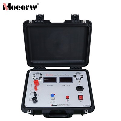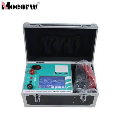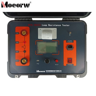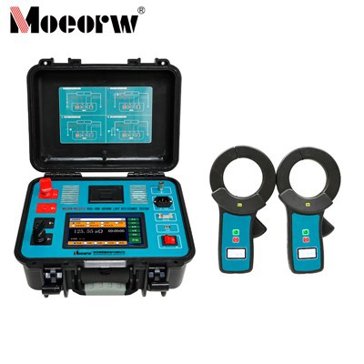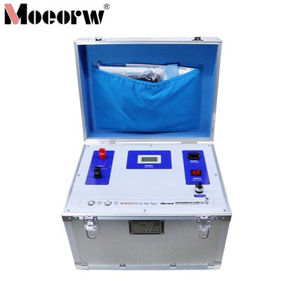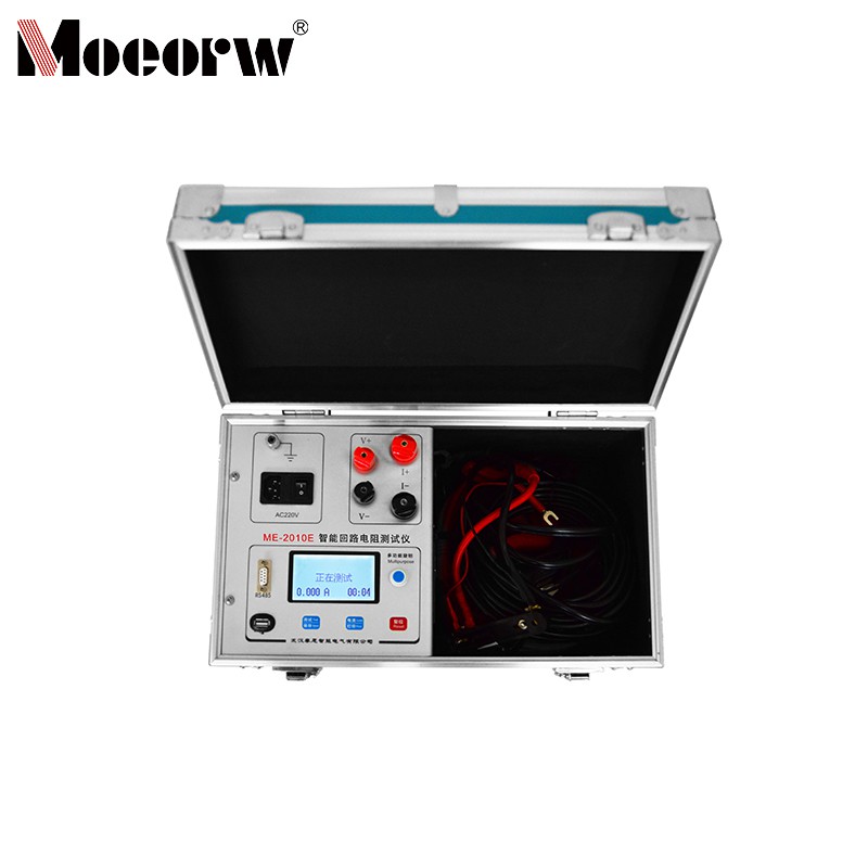


(100A) Smart Loop Resistance Tester
Product Introduction
The electrical conductivity of a circuit breaker's (hereinafter referred to as switch) conductive circuit plays a crucial role in ensuring the safe operation of the switch. The quality of electrical conductivity can be reflected by the magnitude of the conductive circuit resistance. Therefore, IEC standards and manufacturers stipulate that circuit resistance must be measured, with explicit specified targets for circuit resistance across various switch types. Traditionally, the double-arm bridge method was employed. However, due to the bridge's relatively low voltage and current capabilities, test data dispersion increases significantly when contaminants or surface oxidation exist between the switch's moving and stationary contacts. Additionally, the bridge exhibits poor resistance to interference. Consequently, both GB50150-91 and DL/T596-1996 stipulate the use of the "direct current voltage method" with "current not less than 100 amperes." The ME-W2010E (100A) Intelligent Loop Resistance Tester, developed by our company to meet regulatory requirements, is widely applicable for measuring contact resistance, loop resistance of various electrical switches, as well as contact resistance of cables, wires, and welded joints.
Product Parameter (specification)
|
1. Test Current |
50A, 100A |
|
2. Measurement Range |
50A Range;0 to 100 mΩ 100A Range;0 to 50 mΩ |
|
3. Minimum Resolution |
0.01μΩ |
|
4. Accuracy |
0.5% ± 0.2μΩ |
|
5. Output Voltage |
DC 10V |
|
6. Operating Mode |
100A, 50A continuous |
|
7. Power Supply |
AC 220V ±10%, 50Hz |
|
8. Power consumption |
≤1000W |
|
9. Operating temperature |
-20°C to 40°C |
|
10. Relative humidity |
≤80%, non-condensing |
|
11. Weight |
8.5kg |
|
12. Dimensions |
360mm × 235mm × 270mm |
Product feature and application
1. High test current fully complies with national standards for contact resistance testing.
2. High output voltage with wide measurement range up to 100mΩ.
3. Test current sourced from a high-precision 100A switching constant-current power supply, eliminating manual adjustment for rapid and accurate testing.
4. Four-terminal wiring method effectively eliminates the influence of test lead resistance on results.
5. Fast testing speed with data displayed in approximately 3 seconds.
6. Supports extended continuous operation with built-in overheat protection circuit for reliable and stable performance.
7. Simple operation and lightweight design make it ideal for field applications.
8. Features a perpetual calendar and 99-group data storage with non-volatile memory. Equipped with a USB port for convenient data export to computers for spreadsheet generation.
9. Incorporates an RS485 communication interface for remote measurement control via host computer software.
Prodection details
Application Scenarios
This instrument strictly complies with GB50150-91, DL/T596-1996, and relevant IEC standards. Utilizing the 100A high-current DC voltage drop method as its core testing principle, it is suitable for precise resistance measurement in the following scenarios:
1. Power Systems:
Testing contact resistance and loop resistance of high-voltage electrical switches such as circuit breakers, disconnect switches, and load switches to ensure safe and stable operation of power equipment;
01
2. Electrical Manufacturing:
Factory acceptance testing of loop resistance for electrical equipment like high/low-voltage switchgear, distribution boxes, and bus ducts during production, as well as quality sampling inspections of finished products;
02
3. Cables & Welding:
Measurement of conductor resistance in cables and wires, contact resistance at joints, and detection of contact resistance at welds and copper/aluminum busbar connection points to identify connection hazards;
03
4. Operation & Maintenance:
Periodic inspections, fault troubleshooting, and post-repair loop resistance verification for electrical equipment in substations, power plants, industrial facilities, and mining operations;
04
5. Field Operations:
The instrument's lightweight portability and user-friendly operation meet resistance measurement needs in outdoor construction sites, remote power supply locations, and other environments without fixed testing infrastructure.
05
Company Qualifications
Hot Tags: intelligent contact resistance tester, China intelligent contact resistance tester manufacturers, factory, 600A Contact Resistance Tester, Handheld Contact Resistance Tester, High Precision Contact Resistance Tester, switch gear test equipment, Vacuum Degree Tester for Vacuum Breaker, Vacuum Switch Interrupter Vacuity Tester