


Handheld DC Loop Resistance Tester
Product Overview
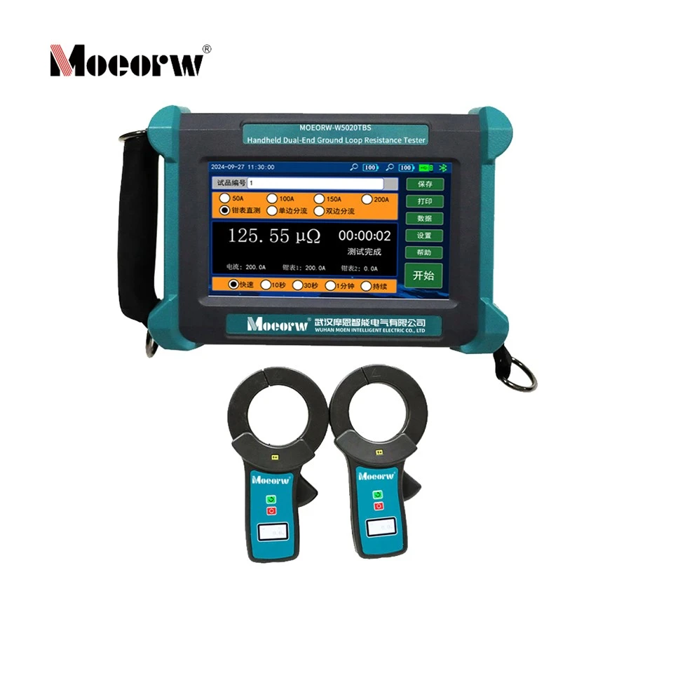
MOEORW-W5020TBS handheld loop resistance tester is developed complying with China's power industry standard DL/T845.4-2019, designed for high-precision DC loop resistance measurement of high-voltage circuit breakers and switchgear. The core innovative design supports single-side and double-side grounded testing without disassembly of earthing busbars, eliminating potential electric shock risks induced by stray induced voltage during field maintenance. Equipped with built-in rechargeable lithium battery and wireless clamp meter supporting non-contact DC current acquisition, the device realizes traditional four-wire test and intelligent shunt measurement, drastically shortening on-site test workload for power grid operation & maintenance departments and high-voltage switch manufacturers.The instrument adopts 7-inch high-brightness color touch LCD with sunlight-readable display, high-speed MCU centralized control and multi-level safety protection circuit, featuring stable measurement accuracy and complete data storage & export functions with voice result broadcast after each measurement cycle.
Working Principle
The tester covers four independent testing principles split into two major test modes:
1. Traditional Loop Resistance Mode: Standard four-wire DC resistance testing. Remove earthing busbar on one side of tested equipment; inject fixed DC current I₁ via I+/I- terminals, collect voltage drop V across test object via V+/V- terminals, calculate resistance: R=V/I₁ per Ohm's law.
2. Intelligent Test Mode (No Earthing Busbar Removal Required)
1. Direct Clamp Measurement: Wireless clamp captures actual effective loop current I₀ bypassing parallel earthing branches, compute R=V/I₀.
2. Single-Sided Shunt Test: Single wireless clamp measures shunt branch current I₂, valid operating current I₀=I₁-I₂, Rx=V/(I₁-I₂).
3. Double-Sided Shunt Test: Dual wireless clamps collect two-way shunt current I₂₁ & I₂₂, valid loop current I₀=I₁-I₂₁-I₂₂, Rx=V/(I₁-I₂₁-I₂₂).
Product Structure Composition
The complete test system consists of main tester unit + wireless Hall-effect DC clamp meters (1# CT1,2# CT2).
Main Unit Front Panel Definition
| Serial No. | Component Name | Functional Description |
| 1 | Earthing Terminal | Reliable equipment grounding for anti-electric-shock protection |
| 2 | Power Switch | Global on/off control for host machine |
| 3 | USB Interface | USB disk access for measured data export (FAT32 format required) |
| 4 | DC Charging Port | DC12.6V external charging input for built-in lithium battery |
| 5 | Speaker Outlet | Voice broadcast output port for test result announcement |
| 6 | Four-Wire Test Terminal | I+/I- for current output, V+/V- for voltage sampling |
| 7 | Color Touch LCD | Parameter setup, real-time data display and operation control |
Wireless Clamp Meter Structure
- Zero-calibration button: Reset clamp meter zero drift before measurement;· Power key: Independent power control for wireless CT;· LCD screen: Real-time remaining battery, measured DC current value and CT serial number display;· Clamp jaw: Φ68mm inner diameter for cable clamping, forward current inflow defines positive measurement polarity.
Technical Specifications
Host Main Technical Parameters
| Parameter Item | Detailed Specification |
| Output Test Current | Adjustable:50A/100A/150A/200A; Intelligent mode fixed at 200A |
| Measurement Range | 5μΩ~25mΩ(50A);5μΩ~10mΩ(100A);5μΩ~5mΩ(150A);5μΩ~2mΩ(200A) |
| Minimum Resolution | 0.01μΩ |
| Selectable Test Duration | 50A:Quick/5s/10s/30s/60s100A:Quick/5s/10s/30s150A:Quick/5s/10s200A:Quick/5sIntelligent Mode:≤5s (fixed, no option) |
| Measurement Accuracy | Traditional Mode:±(0.5%×Reading+0.2μΩ)Intelligent Mode:±(2%×Reading+0.5μΩ) |
| Operating Ambient Temp | -10℃ ~ +50℃ |
| Relative Humidity | ≤90%RH, non-condensing |
| Built-in Power Supply | Lithium battery, rated charging voltage DC12.6V |
| Host Dimension | 235mm×165mm×75mm |
| Net Weight of Main Unit | 2.0kg |
| Internal Storage | 512 groups of test data |
| Overheat Protection Threshold | 70℃ for power device & battery overheat cutoff |
Wireless Clamp Meter Parameters
| Parameter Item | Specification |
| Measuring Principle | Hall-effect non-contact DC detection |
| DC Current Measuring Range | 0~±600A |
| Measurement Precision | ±(2%×Reading+0.5A) |
| Current Resolution | 0.01A |
| Clamp Inner Diameter | Φ68mm |
| Power Supply | Independent built-in rechargeable lithium cell |
Core Features
1. Hardware & Structural Design
- Equipped with 7-inch high-brightness industrial color touch screen with anti-glare coating to ensure clear data reading under direct sunlight; high-speed embedded microchip realizes automatic parameter matching and full-process automated testing.· Integrated multi-layer protection circuit including overcurrent, short-circuit and over-temperature cutoff; battery low-power auto-lock protection stops all test functions to avoid abnormal discharge damage.· Independent built-in non-volatile storage chip supporting 512-group offline data storage, matched with USB data export channel for external data archiving.· Standard voice broadcast module automatically announces final resistance reading upon completion of each testing cycle.
2. Performance Advantages
- Max 200A stable DC output current with subdivided four-level current gears to adapt different resistance-range test specimens; minimum 0.01μΩ resolution meets ultra-low resistance precision test requirement for HV switch contacts.· Dual test architecture (traditional + intelligent measurement) covers diversified on-site working conditions; intelligent shunt series modes eliminate mandatory earthing busbar disassembly.
3. Practical Application Value
- Intelligent test mode avoids false grounding hidden danger caused by incomplete earthing disassembly in traditional test, effectively lowering field operator's electric shock accident probability.· No disassembly operation reduces overall on-site testing time by over 60%, improves maintenance efficiency for substation routine overhaul and factory incoming inspection of high-voltage switches.· Built-in real-time clock module marks timestamp for every stored data, convenient for later data traceability, sorting and report compilation.
Application Fields
1. Routine loop resistance preventive test of high-voltage AC/DC circuit breakers, disconnecting switches and earthing switches in power substations;2. Factory outgoing inspection of HV switch manufacturers for contact loop resistance verification;3. Field maintenance test for distribution cabinet, GIS equipment and high-voltage switchgear in industrial power plants, metallurgy and petrochemical enterprise self-owned power stations;4. Power grid acceptance inspection for newly-built transformer substation switch equipment.
Applicable Industry Standard
Designed and tested strictly in accordance with DL/T845.4-2019 Measurement methods for resistance of electrical equipment in power system Part 4: Loop resistance tester, fully satisfying domestic power industry acceptance and inspection specification requirements.
Standard Accessories (Per Original Manual Configuration)
1. Main tester ×1 set;2. 1# & 2# wireless DC clamp meter ×2pcs;3. Four-wire dedicated test leads (red V+/I+, black V-/I-) ×1 group;4. Equipment earthing cable ×1pc;5. DC12.6V dedicated charging adapter ×1pc;6. Portable storage suitcase for instrument and accessories.
Daily Maintenance Specification
1. Physical maintenance: Store instrument indoors under dry environment; avoid heavy impact, inversion or overweight stacking on equipment shell during transportation and use.2. Pre-inspection before field test: Verify residual power of two wireless clamp meters fully to prevent power failure interrupting field measurement; fully unfold all test leads instead of coiling during connection to reduce extra line resistance error.3. Post-operation maintenance: Power off host before disconnecting all test cables and earthing wire; tidy all accessories and place into matched storage case after each test.4. Periodic calibration: Perform clamp zero calibration via host setting menu regularly when obvious measurement deviation occurs for clamp meter.
FAQ
Q1: Why intelligent mode test result is only for reference when measured effective loop current is below 100A?
A: The instrument's intelligent test algorithm is designed based on ≥100A effective loop current; low working current will increase calculation deviation beyond specified accuracy range.
Q2: How to calibrate zero drift of wireless clamp meter?
A: Connect host I+ and I- terminals with short-circuit wire, turn on target clamp meter and fasten on short-circuit wire, enter calibration menu in host setting interface to complete auto zeroing following on-screen prompt.
Q3: The host prohibits starting test automatically, what is the common reason?
A: Built-in lithium battery enters low-power over-discharge protection mode, recharge the host with matched DC12.6V power adapter.
Q4: Measurement prompts error after wiring completion?
A: Check four-wire wiring order; ensure voltage sampling leads (V+/V-) are laid inside current output leads (I+/I-) and all terminals are fastened tightly without loose contact.
Q5: Can wireless clamp meter measure AC current?
A: No, the clamp is dedicated for DC current detection within DC0~±600A range; over-range input will cause permanent hardware damage.
Hot Tags: handheld dual-end ground loop resistance tester, China handheld dual-end ground loop resistance tester manufacturers, factory, 600A Contact Resistance Tester, Color Touch Screen Loop Resistance Tester, Compact Handheld Loop Resistance Tester, Handheld Contact Resistance Tester, RCD test meters, Two terminal Ground Loop Resistance Tester