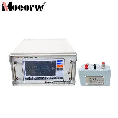
product Introduction
The MOEORW-WGUC UHF Partial Discharge Calibration System is a highly integrated, professional-grade platform engineered specifically for verifying, benchmarking, and calibrating the performance of Ultra-High Frequency (UHF) partial discharge (PD) detection instruments.
Integrating state-of-the-art signal synthesis, high-precision measurement topologies, and automated evaluation algorithms, this system provides comprehensive and traceably precise assessment for UHF detection equipment, guaranteeing operational reliability in structural health monitoring and live field inspections.
The system's core parameters fully comply with utility standard frameworks, including State Grid Q/GDW 11304.8-2019 (Technical Specifications for Energized Test Instruments of Power Equipment - Part 8: UHF Partial Discharge Detector) and industry standard DL/T 1630-2016 (Technical Specification for UHF Partial Discharge Detection in Gas Insulated Metal-Enclosed Switchgear). It serves as a benchmark metrology solution to support data-driven asset management and precise condition assessment for smart grids.
Product Parameter (Specification)
2.1 System Mainframe
Dimensions (L × W × H): ≥ 800 mm × 800 mm × 1800 mm
Form Factor: All-in-one integrated console with internal routing and modular slide-in bays.
Shielding Effectiveness: ≥ 50 dB (14 kHz to 1 GHz)
Grounding Resistance: ≤ 1 Ω
I/O Interfaces: 4 × BNC universal switchable ports (software-controlled matrix switching).
Control Interconnects: Support for Ethernet, USB wired connections, and Wi-Fi / Bluetooth wireless networking.
Switching Architecture: Dual-layer shielded pneumatic isolation switching to eliminate electromagnetic interference.
2.2 Signal Output Unit
Pulse Output Amplitude: 0 V to ≥ 80 V continuous adjustment
Pulse Rise Time (tr): ≤ 300 ps (Ultra-fast edge)
Pulse Width (FWHM / Full Width at Half Maximum): 4 ns to 100 ns
Pulse Repetition Frequency (PRF): 1 Hz to ≥ 300 Hz
Output Modes: Single pulse, continuous firing, and frequency sweeping.
Defect Simulation Capability: Pre-programmable 50-group PRPS/PRPD patterns looping sequentially to simulate real-world defects (corona/sharp-point, floating potential, particle, void, and surface discharges).
Interference Simulation Capability: Emulation of background white noise, SCR pulses, motor sparking, and radio-frequency interference (RFI).
2.3 Smart Analysis Module
Analog Bandwidth: 4 GHz
Real-time Sampling Rate: 10 GSa/s
Max Memory Depth: 250 Mpts/ch
Max Waveform Capture Rate: 500,000 wfm/s
Vertical Resolution: 8-bit
Product Feature
All-in-One Structural Integration: Features a fully integrated console design. Users complete the physical wiring matrix just once, and the software automatically runs all verification items without manual cable swapping.
Comprehensive Multi-Dimensional Validation: Fully capable of measuring sensor average effective height (Heff), input detection sensitivity, dynamic response ranges, PD pattern classification accuracy, and long-term operational stability.
Pure Signal Pathway via Pneumatic Switching: Employs pneumatic-driven switches instead of traditional electromagnetic relays. Coupled with an advanced dual-layer aluminum alloy shield, it isolates structural control signals from high-frequency test paths, maintaining unmatched signal integrity.
Smart Verification Engine: Powered by a customized C/S architecture application. Features parametric waveform editing (manual canvas drawing or spectrum/image importing), automatic metric computation, threshold pass/fail judgment, and automated standardized PDF report generation.
Robust Multi-Mode Power Architecture: Equipped with a smart-switching dual power system. Seamlessly transitions between standard utility power (220V/50Hz) and an onboard internal battery pack, ensuring reliable field deployment in harsh switchyard conditions.
Product Application

Grid Asset Metrology & Calibration Laboratories: Used by national, provincial, or third-party electrical metrology institutes to periodically calibrate and certify portable or online UHF partial discharge diagnostic tools.
GIS / GIL Quality Assurance Testing: Serves equipment manufacturers and field testing crews to verify the absolute sensitivity of internal or external UHF sensors installed on Gas Insulated Switchgear (GIS) and Gas Insulated Lines (GIL) before commissioning.
PD Diagnostic Instrument Development & QA: Used by high-voltage test equipment R&D departments to baseline signal capture logic, train AI defect-recognition classifiers (pattern recognition algorithms), and test anti-jamming filters against multi-frequency environmental noise.
Substation Commissioning and Preventive Maintenance: Validates field-deployed (live inspection) instruments, ensuring high signal-to-noise ratios (SNR) and standardized data comparability when diagnosing high-risk insulation faults.
Key System Modules
5.1 Giga-Hertz Transverse Electromagnetic
Structural Design: Designed as a tapered, non-symmetrical rectangular coaxial transmission line to suppress internal electromagnetic wave reflections and resonance.
Core Plate & Field Uniformity: Features a flattened fan-shaped septum (inner conductor) that establishes an extremely uniform rectangular electromagnetic field testing zone between the septum and the bottom plate, approximating an ideal plane wave.
Non-Reflective Termination: Terminated with a highly reliable distributed resistor matching network and lined with advanced RF absorbing materials at the end wall to ensure perfect impedance matching and zero wave reflection across the 300 MHz to 3 GHz spectrum.
5.2 Standard Reference Sensor / Monopole Probe
Signal Fidelity: Engineered with an ultra-linear, non-distorting receiving characteristic to serve as the absolute metrological baseline for sensor effective height (Heff) verification.
Physical Dimension: Precision-machined monopole probe with a radius (r) of 0.65 mm and a physical height (h) of 25 mm, providing a traceable and verifiable transfer function curve.
5.3 Measurement & Control Software Architecture
Architecture Topography: Built upon a highly secure Client/Server (C/S) architecture. The client frontend handles intensive user interaction and real-time instrumentation telemetry, while the backend server drives advanced calibration engines and algorithm execution.
Data Interconnect & Safety: Implements bidirectional data streams via secure TCP/IP sockets with sub-millisecond latency. Features native enterprise-grade data management backed by a SQL database engine, offering multi-version historical data traceability and robust Role-Based Access Control (RBAC).
Verification & Calibration Workflow
The system features a fully automated, single-connection testing sequence governed by the smart software suite:
Initialization & Self-Check: Comprehensive automated diagnostic routine upon system boot to ensure all RF switching networks, signal sources, and digitization hardware are in a calibrated baseline state.
One-Time Wiring Setup: The device under test (DUT) and its corresponding UHF sensors are connected to the Smart Switching Module just once.
Automated Sequence Execution: The software automatically sequences through the preset standard matrices (Effective Height → Sensitivity → Dynamic Range → Pattern Recognition Accuracy → 4-Hour Stability).
Algorithmic Evaluation & Report Pass/Fail: The localized software engine parses data streams from the DUT, evaluates metrics against predefined Q/GDW or IEC thresholds, and automatically compiles exportable, tamper-proof calibration certificates.
FAQ
Q1: Which international or industry standards does this calibration system comply with?
A: The MOEORW-WGUC system is deeply aligned with the latest global smart grid testing frameworks. It strictly complies with state/utility metrology directives, including Q/GDW 11304.8-2019 and DL/T 1630-2016. Furthermore, its foundational measurement methodology for sensor effective height (Heff) and field uniformity satisfies the technical requirements specified in IEC TS 62478 (High-voltage test techniques - Electromagnetic partial discharge measurements).
Q2: Why does the system use a GTEM cell instead of a standard TEM cell or an anechoic chamber?
A: A GTEM (Giga-Hertz Transverse Electromagnetic) cell offers the optimal environment for high-frequency UHF PD testing (300 MHz to 3 GHz). Unlike a standard TEM cell, which suffers from modal resonance above a few hundred megahertz, the tapered design of our GTEM cell, combined with its specialized distributed resistor matching network and advanced RF absorbing linings, provides zero-reflection plane-wave emulation and superior field uniformity across the entire gigahertz spectrum. It provides an ideal shielded environment without the immense space and cost of a full anechoic chamber.
Q3: What is the purpose of the "Smart Switching Module" and the "One-Time Wiring" feature?
A: Traditional calibration setups require operators to manually swap coaxial cables between testing different metrics (e.g., changing from the reference sensor to the test sensor), which is time-consuming and introduces error. Our Smart Switching Module routes all internal paths automatically via software matrix control. You complete the physical wiring matrix just once, and the system executes the entire suite of trials (Effective Height, Sensitivity, Dynamic Range, Stability) automatically.
Q4: How does the system prevent its own internal relays from introducing electromagnetic interference (EMI) during ultra-sensitive UHF tests?
A: This is a key technical highlight of our platform. Instead of standard electromagnetic relays-our system employs a pneumatic-driven switching architecture. The electrical control signals are completely isolated from the RF pathway through dual-layer aluminum alloy shielding, achieving zero-cross-talk and preserving unmatched signal purity for picosecond-level pulse verifications.
Q5: Can the system simulate real-world field conditions and defect types, or does it only output standard single pulses?
A: It is fully capable of real-world defect emulation. While it features a standard fast-edge pulse generator (tr≤300ps), its core synthesis engine supports parametric pattern programming. It comes pre-loaded with 50-group cyclic PRPS/PRPD patterns to dynamically simulate typical GIS faults, such as:Floating potential dischargesFree metallic moving particlesSharp metallic points / corona dischargesVoids / internal gas-gap insulation defectsSurface flashovers / trackingIt can also overlay simulated environmental noise (such as radio-frequency interference or SCR pulses) to evaluate the anti-jamming classifiers of your instrument.
Q6: Is the software compatible with third-party digital data capture systems or local databases?
A: Yes. The control software is built on a modern Client/Server (C/S) architecture utilizing native SQL database backends. It supports multi-user role-based access controls and tracks comprehensive multi-version historical data. For data interconnectivity, the platform provides open APIs capable of ingesting, parsing, and exchanging testing vectors across software modules written in C#, Java, or Python.
Q7: Can this system be deployed for harsh field environments, or is it strictly for calibration labs?
A: It is designed for both. While its metrological precision matches standard calibration laboratories, the entire system is housed in a ruggedized, fully shielded mobile enclosure with heavy-duty castors. Crucially, it features a dual-mode smart power layout that seamlessly switches to its integrated internal battery package when utility power (220V AC) is unavailable in remote high-voltage substations or new switchyards.
Hot Tags: automated calibration system for uhf partial discharge detectors, China automated calibration system for uhf partial discharge detectors manufacturers, factory