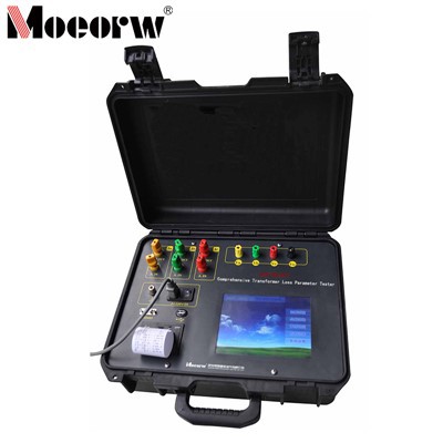
Compact PD Tester for Transformer Factory: The Complete Guide to Offline & Live Partial Discharge Testing
A compact PD tester for transformer factory use lets quality and test engineers measure partial discharge (PD) two ways: as a calibrated offline acceptance test on the production floor, and as a portable live inspection tool on energised assets. This guide explains what PD is, the two testing paradigms, the sensor technologies behind modern compact instruments, how to diagnose discharge types, and a repeatable workflow your factory can standardise.
Definition: A partial discharge (PD) is a localized electrical discharge that partially bridges the insulation between conductors but does not fully break it down. In transformers, PD is an early warning of voids, cracks, loose contacts or contaminated insulation - the root causes of field failures. PD is widely recognised as a primary mechanism of long-term insulation degradation and eventual failure, which is why measuring it is part of the factory acceptance routine for most high-voltage equipment.
Why Transformer Factories Need Compact PD Testing
1. Offline factory acceptance (IEC 60270)
Before shipment, power transformers undergo dielectric tests. PD measurement is a standard part of the program, referenced by IEC 60076-3 (insulation levels, dielectric tests and external clearances) with measurement performed per IEC 60270. A compact tester makes it practical to run PD checks on relevant units rather than only on type tests.
2. Live, non-contact inspection
Once a transformer is installed - or for a factory's own substation and incoming/outgoing switchgear - a compact multi-sensor detector can find PD on energised equipment without an outage. This supports condition-based maintenance and early fault prediction.
Two PD Testing Paradigms
| Aspect | Offline acceptance (IEC 60270) | Live inspection (multi-sensor) |
|---|---|---|
| When | Before energisation, in test bay | On energised assets, in service |
| Measured quantity | Apparent charge (pC), calibrated | TEV / UHF / HFCT / AE signal intensity (dB) |
| Outage required | Yes (test voltage applied) | No |
| Typical output | PD magnitude (pC) + PRPD | PRPD/PRPS patterns, discharge-type tags |
| Best for | Pass/fail acceptance per spec | Trend monitoring, fault localisation |
How Partial Discharge Produces Detectable Signals
A PD event releases energy in several forms, which is why compact detectors use multiple sensor types:
Electromagnetic radiation - radiates from the source; metal panels of switchgear pick it up as a small transient earth voltage (TEV).
Ultrasound / acoustic emission - PD in air (e.g. a tip on an air-insulated cable terminal, a classic corona source) or inside cast-resin generates sound a sensor can detect.
High-frequency current - PD in cables and transformer/breaker ground loops is captured by a clamp-on current sensor.
Sensor Technologies in a Modern Compact PD Tester
| Sensor | Working band | What it detects |
|---|---|---|
| TEV (transient earth voltage) | ~3–100 MHz | PD radiating through metal enclosures of MV/HV switchgear |
| UHF (ultra-high frequency) | 300 MHz–3 GHz | Internal insulation defects inside GIS/switchgear; strong EMI rejection |
| HFCT (high-frequency current transformer) | 1–30 MHz (sensitivity ≤2 pC) | PD in cables, transformers, breaker ground loops |
| AE (acoustic emission, contact) | 20–200 kHz | Surface/insulator/bushing corona on open equipment |
| Ultrasonic (AA) | ~20–60 kHz (centre 40 kHz) | Airborne ultrasound from corona/tip discharges |
| Acoustic imaging / infrared (optional) | visual + thermal | Localise multiple discharge/leak points; spot overheating |
A compact instrument typically fuses these channels and adds PRPD (phase-resolved partial discharge) and PRPS (phase-resolved pulse sequence) charts, plus trend windows, so engineers see both the magnitude and the phase behaviour of discharges.
Diagnosing the Discharge Type
The shape and phase position of the PD pattern let a trained engineer - or a modern instrument's AI classifier - separate typical defect signatures. Common categories a compact PD tester should distinguish:
Free metallic particle discharge - mobile particles inside the insulation.
Floating-potential discharge - loose or poorly grounded components.
Surface (creeping) discharge - tracking along an insulator surface.
Internal void discharge - gas pockets inside solid insulation.
Metallic tip discharge - sharp edges / corona sources.
Corona discharge - in air, often at terminals.
Modern multi-function detectors report a discharge-type tag with a stated recognition rate of around 95% for these typical defects, cutting manual interpretation time. (Verify the claimed accuracy against your own validation before relying on it.)
Key Features to Look for in a Compact PD Tester
| Feature | Why it matters for a transformer factory |
|---|---|
| Battery / tablet operation | Move between test bays and onto site without AC infrastructure. |
| Multi-sensor fusion (TEV+UHF+HFCT+AE) | One unit covers switchgear, GIS, cables and transformers. |
| Integrated IEC 60270 calibration | Traceable apparent-charge results for acceptance tests. |
| PRPD / PRPS visualisation | Pattern recognition separates internal voids from external corona. |
| Noise gating & EMI shielding | Defensible PD values on a noisy factory floor / substation. |
| Non-contact, no-outage mode | Live inspection of energised assets for condition monitoring. |
Compact vs. Traditional PD Test Sets
| Criterion | Compact PD tester | Traditional test bay |
|---|---|---|
| Footprint | Small, case-mounted | Fixed, large |
| Mobility | Factory floor + on-site | Factory only |
| Setup time | Minutes | Longer |
| Live inspection | Yes (TEV/UHF/HFCT/AE) | No |
| Best for | Routine QA + condition monitoring | Full type testing, research |
Step-by-Step: Running a PD Test in a Transformer Factory
A. Offline acceptance (IEC 60270)
Prepare the test object. Ground the tank, connect the HV source, confirm safety clearances.
Connect coupling capacitors / sensors at HV and neutral terminals per the test plan.
Calibrate the circuit per IEC 60270 by injecting a known charge and recording the response.
Ramp voltage to the specified PD test level (commonly 1.5 × Um/√3 or per specification).
Measure and record PD magnitude (pC) and PRPD at the hold voltage for the required duration.
Evaluate against limits and document the phase pattern and noise floor.
Generate the report with calibration data, ambient conditions and PRPD plot.
B. Live inspection (multi-sensor)
Select the sensor for the asset (TEV/UHF for enclosed gear, HFCT for cable grounds, AE for open equipment).
Scan around the enclosure at defined points; the instrument logs TEV/PD intensity and PRPD.
Cross-check with acoustic / infrared to localise the discharge and rule out heating.
Tag the discharge type and compare against the asset's historical baseline (trend analysis).
Interpreting PD Results
Acceptable PD levels depend on voltage class and the procuring specification. Common factory-acceptance limits range from roughly 100 pC for lower-voltage units up to 300–500 pC for higher-voltage classes; the exact pass/fail threshold must follow the purchasing specification and IEC 60076. For live inspection, trend is more important than a single absolute number - a rising PRPD trend over successive surveys is the actionable signal.
Common Mistakes & How to Avoid Them
Skipping calibration → results not traceable. Always calibrate per IEC 60270 before the offline test.
Ignoring the noise floor → false positives. Use gating/filtering and record the noise level.
Reading only peak pC → misdiagnosis. Review the PRPD pattern to classify the discharge type.
Using one sensor for every asset → missed defects. Match TEV/UHF/HFCT/AE to the equipment.
Inconsistent procedure → non-comparable results. Standardise the ramp, hold and scan routine.
Frequently Asked Questions
What is a compact PD tester used for in a transformer factory?
A compact PD tester serves two roles in a transformer factory: (1) offline factory-acceptance measurement of partial discharge in picocoulombs (pC) per IEC 60270, and (2) portable live inspection of in-service transformers and switchgear using TEV, UHF, HFCT and acoustic sensors without taking equipment out of service.
What standard covers partial discharge measurement?
Offline PD measurement is governed by IEC 60270. Transformer factory tests are referenced in IEC 60076-3. Many buyers also require IEEE C57.113 for PD measurement on power transformers.
What PD level is acceptable for a power transformer?
Acceptable PD levels depend on voltage class and the purchasing specification. Common factory-acceptance limits range from roughly 100 pC for lower-voltage units up to 300–500 pC for higher-voltage classes; the exact pass/fail threshold must follow the specification and IEC 60076.
What is the difference between TEV, UHF, HFCT and AE PD sensors?
TEV (transient earth voltage, ~3–100 MHz) picks up PD radiated through metal enclosures; UHF (300 MHz–3 GHz) detects internal defects inside GIS/switchgear; HFCT (1–30 MHz, sensitivity ≤2 pC) clamps on ground leads to catch cable/transformer PD; AE (20–200 kHz) is a contact ultrasonic sensor for open equipment. Each fits a different asset and access condition.
Can PD testing be done without shutting down the transformer?
Yes. Live, non-contact PD inspection uses TEV, UHF, HFCT and acoustic sensors to detect partial discharge on energised equipment, so no outage is required. This is complementary to offline IEC 60270 acceptance testing performed before the unit is energised.
Why choose a compact or portable PD tester over a traditional test set?
Compact PD testers integrate coupling, filtering, calibration and analysis in a small, battery- or tablet-controlled unit. They move between test bays and onto the factory floor or substation, shortening setup time for routine QA and enabling live inspection.
Featured: MOEORW-Wi900PD Multi-Function PD Detector
For transformer factories that need both offline acceptance and live inspection in one instrument, the MOEORW-Wi900PD is a compact, non-contact detector built for switchgear, GIS, transformers and cables.
| Capability | Specification |
|---|---|
| Detection modes | TEV, UHF, HFCT, AE, ultrasonic (AA), infrared thermography, SF6 (optional) |
| TEV | 3–100 MHz, dynamic range 0–65 dB |
| UHF | 300 MHz–3 GHz, gain +5 dBi, sensitivity 0.39 V/m |
| HFCT | 1–30 MHz, sensitivity ≤2 pC, IP61 |
| AE / ultrasonic | 20–200 kHz / 20–60 kHz (centre 40 kHz) |
| Sampling & sync | 200 MS/s; internal/external sync 20–350 Hz (±0.01 Hz) |
| Diagnosis | PRPD / PRPS; AI classification of 6 discharge types, ~95% recognition rate |
| Infrared (optional) | 512×384, −20 °C to 450 °C, high/low-temp alarm |
| Operation | Non-contact, no outage; tablet/phone app reporting, QR asset ID |
Specifications are taken from the MOEORW-Wi900PD manual; confirm the current datasheet before publishing or quoting.
Conclusion
A compact PD tester for transformer factory use turns partial discharge testing from a fixed-bay, type-test activity into a routine, portable quality step - covering both offline IEC 60270 acceptance and live, non-contact inspection. For factories targeting defensible, standards-based results, the deciding factors are integrated calibration, multi-sensor coverage (TEV/UHF/HFCT/AE), strong noise rejection, and clear PRPD/PRPS reporting. A purpose-built example is the MOEORW-Wi900PD multi-function partial discharge detector: it fuses TEV (3–100 MHz), UHF (300 MHz–3 GHz), HFCT (sensitivity ≤2 pC, 1–30 MHz), AE (20–200 kHz) and ultrasonic sensing in one portable, non-contact instrument, delivers PRPD/PRPS charts, and uses AI to tag the six typical discharge types - all without taking the asset out of service.
Contact our engineering team for a test-plan review. (Verify all product specifications, voltage classes, sensor bands and PD limits against your purchasing specification and the actual instrument datasheet before use.)