Product Overview
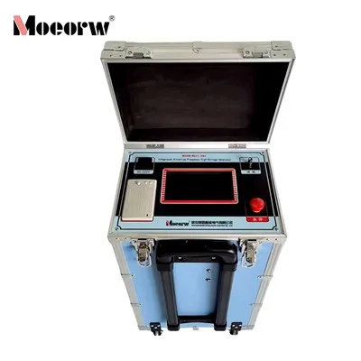
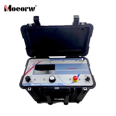
The MOEORW-WHVA81 is a VLF hipot tester that integrates AC/DC withstand voltage, tan delta (dielectric loss) , capacitance, insulation resistance, and partial discharge (PD) measurement in a single unit. Designed for high-capacitance loads such as power cables and electric motors, it employs digital frequency conversion and microcontroller-based automation for voltage ramping, measurement, and protection. Voltage and current are sampled directly from the high-voltage side with closed-loop control to eliminate capacitive rise effects. Intelligent auto-protection calculates thresholds based on load capacitance, safeguarding against overvoltage, overcurrent, faults, and flashover. The large touchscreen interface provides intuitive control and real-time waveform display. During AC/DC testing, the system simultaneously measures tan δ, capacitance, insulation resistance, and PD, enabling comprehensive insulation assessment in a single session. Note: This instrument is not suitable for resistive test objects such as zinc oxide surge arresters.
Technical Specifications
VLF High Voltage Power Supply
|
Parameter |
Specification |
|
Rated Output Voltage (Peak) |
80 kV |
|
Output Frequency Range (Automatic) |
0.1 Hz – 0.01 Hz |
|
Load Capacity (at 0.1 Hz) |
≤ 5 μF |
|
AC Voltage Resolution |
0.1 kV |
|
AC Voltage Accuracy |
±3% |
|
AC Current Resolution |
0.1 mA |
|
AC Current Accuracy |
±3% |
|
Positive/Negative Peak Voltage Error |
≤3% |
|
Voltage Waveform Distortion |
≤3% |
|
Input Power Supply |
220V ±5% / 50Hz or 110V ±5% / 60Hz |
|
Operating Temperature |
-10°C to +40°C |
|
Operating Humidity |
≤85% RH |
|
Controller Weight |
5 kg |
|
HV Unit Weight |
65 kg |
Note: When powered by a portable generator, a frequency-stabilized (inverter) generator must be used. Standard generators with unstable rotational speed may cause abnormal voltage output and damage the instrument.
Tan Delta (Dielectric Loss) Measurement
|
Parameter |
Specification |
|
Test Voltage Range |
1 kV to Rated Value |
|
Test Frequency |
0.1 Hz – 0.01 Hz |
|
Tan δ Measurement Range |
0.01×10⁻³ to 655.35×10⁻³ |
|
Tan δ Measurement Accuracy |
±1% |
|
Tan δ Resolution |
1×10⁻⁵ |
|
Capacitance Measurement Range |
0.001 μF – 10 μF |
|
Capacitance Resolution |
0.001 μF |
|
Capacitance Accuracy |
±3% |
|
Insulation Resistance Range |
1 MΩ – 65535 MΩ |
|
Insulation Resistance Resolution |
1 MΩ |
|
Insulation Resistance Accuracy |
±3% |
|
Communication Interface |
RS232 (or USB) |
Note: Values exceeding 655.35×10⁻³ for tan δ and 65535 MΩ for insulation resistance are displayed with a ">" indicator.
DC Withstand Voltage Test
|
Parameter |
Specification |
|
Rated Output Voltage |
30 kV – 80 kV (model dependent) |
|
Voltage Accuracy |
±3% |
|
DC Leakage Current Range |
0 – 2000 μA |
|
DC Leakage Current Resolution |
1 μA |
|
DC Leakage Current Accuracy |
±3% |
Partial Discharge (PD) Measurement
|
Parameter |
Specification |
|
PD Measurement Range |
0 – 5000 pC |
|
PD Resolution |
1 pC |
|
Sampling Resolution |
12-bit |
|
Sampling Rate |
200 MHz |
|
Discharge Pulse Frequency Range |
1 kHz – 2000 kHz |
|
Display |
Instantaneous and peak PD values; discharge inception/extinction voltage |
General
|
Parameter |
Specification |
|
Voltage Setting Range |
1 kV to Rated Value |
|
Test Time Setting |
1 – 99 minutes |
|
Protection Functions |
Overvoltage, overcurrent, sudden voltage/current change, flashover |
|
Application |
Indoor and outdoor |
|
Power Supply Options |
220V±5% / 50Hz or 110V±5% / 60Hz |
Key Features
Integrated Multi-Function Architecture
The MOEORW-HVA81 consolidates AC withstand voltage, DC withstand voltage, tan δ measurement, capacitance measurement, insulation resistance measurement, and partial discharge detection into a single integrated unit. This monolithic design eliminates the need for separate external test modules, reducing field setup complexity and overall system weight.
High-Voltage Side Direct Sampling
Current and voltage data are acquired directly from the high-voltage side of the test circuit. The closed-loop negative feedback control architecture ensures that output measurements are free from capacitive rise effects, providing accurate and reliable data even when testing long cable runs with significant capacitance.
Automatic Frequency Selection
The system automatically selects the optimal test frequency within the 0.1 Hz to 0.01 Hz range based on the electrical characteristics of the test object. This adaptive frequency capability ensures stable sinusoidal voltage output across a wide range of cable lengths and load conditions.
Intelligent Auto-Protection System
The instrument features a comprehensive protection system that does not require manual configuration of overvoltage or overcurrent thresholds. Protection values are automatically calculated based on the test object's measured capacitance and the applied test voltage. The system provides automatic shutdown protection against:
- Overvoltage conditions
- Overcurrent conditions
- Low-impedance faults in the test object
- Flashover events
Simultaneous Tan Delta and PD Measurement
During AC and DC withstand voltage testing, the system concurrently measures tan δ (dielectric loss factor), capacitance, insulation resistance, and partial discharge levels. This parallel measurement capability enables comprehensive insulation condition assessment without extending test duration.
Standard-Compliant Test Routines
The instrument incorporates automated test sequences compliant with T/CEC-243-2019, Q/CSG1205027-2020, and IEEE 400.2 standards. The "Standard Tan Delta Test" program automatically performs measurements at 0.5U₀, U₀, and 1.5U₀ voltage levels, calculates tan δ averages, variations, and stability indices, and generates a cable insulation condition report classifying results as Normal, Attention, or Abnormal.
Shield Compensation for Surface Leakage
The system supports both single-ended and double-ended shield connections to eliminate the influence of surface leakage current on tan δ measurements under high-humidity conditions or when cable terminations are contaminated. The single-ended method measures near-end leakage and compensates by deducting twice the measured value; the double-ended method measures leakage at both ends simultaneously.
Touchscreen User Interface
A large-format color touchscreen provides intuitive control and real-time visualization of test parameters and output waveforms. Built-in contextual help information guides operators through each step of the test procedure. The interface displays instrument status, fault messages, and measurement data in a clear, organized layout.
Data Management and Reporting
The instrument features an internal thermal printer for on-site report generation. Test data can be saved internally and retrieved via the historical data query function. An RS232 (or USB) communication interface enables data transfer for off-line analysis and documentation.
Applications
Power Cable Testing
- AC withstand voltage testing of medium-voltage power cables (up to 35 kV rated)
- Dielectric loss (tan δ) measurement for insulation condition assessment
- Partial discharge detection for identifying localized insulation defects
- DC withstand voltage and leakage current measurement
- Commissioning tests for newly installed cable systems
- Diagnostic testing for in-service cable aging assessment
Electric Motor Testing
- AC withstand voltage testing of large-capacitance motors
- Insulation resistance measurement
- Tan δ measurement for winding insulation condition assessment
- Partial discharge detection for stator winding insulation evaluation
Other High-Capacitance Apparatus
- Capacitive test objects requiring VLF AC withstand voltage testing
- Electrical apparatus where conventional power-frequency testing is impractical due to high capacitance
Note: The MOEORW-HVA81 is not suitable for resistive test objects such as zinc oxide surge arresters.
Standards and Compliance
The MOEORW-HVA81 is designed and tested in accordance with the following standards and technical specifications:
|
Standard |
Description |
|
T/CEC-243-2019 |
China Electricity Council Standard – Technical specification for VLF dielectric loss testing of power cables |
|
Q/CSG1205027-2020 |
China Southern Power Grid Enterprise Standard – Technical specification for cable insulation testing |
|
IEEE 400.2 |
IEEE Guide for Field Testing of Shielded Power Cable Systems Using Very Low Frequency (VLF) |
The instrument's "Standard Tan Delta Test" program is specifically developed to comply with the test procedures and evaluation criteria defined in these standards, including:
- Measurement at 0.5U₀, U₀, and 1.5U₀ voltage levels
- Calculation of tan δ average values at U₀
- Calculation of tan δ variation between 1.5U₀ and 0.5U₀ measurements
- Calculation of tan δ stability (standard deviation) at U₀
- Automatic cable insulation condition classification
Product Structure
The MOEORW-HVA81 consists of two primary units:
Controller Unit (5 kg) – A compact control console featuring:
- Large-format color touchscreen display
- Microcontroller-based control system
- Thermal printer for on-site reporting
- RS232 (or USB) communication interface
- Input power supply connection
High-Voltage Unit (65 kg) – A heavy-duty cylindrical assembly containing:
- High-voltage step-up transformer
- Power electronics for frequency conversion
- High-voltage output connection (150 kV rated cable)
- Integrated tan δ measurement circuitry
- Integrated partial discharge detection circuitry
High-Voltage Output Cable – 150 kV rated high-voltage cable for safe and reliable connection to the test object.
Standard Accessories
The MOEORW-HVA81 is supplied with the following standard accessories:
|
Accessory |
Description |
|
High-Voltage Output Cable |
150 kV rated high-voltage cable |
|
Grounding Rod |
Manual discharge rod for safe discharging of test object |
|
Compensation Capacitor |
For cables shorter than 200 metres to ensure smooth sinusoidal output |
|
Shield Connection Cables |
For single-ended and double-ended shield connections |
|
Input Power Cable |
AC power supply cable |
|
Thermal Paper Roll |
Replacement paper for internal printer |
|
User Manual |
Comprehensive operating instructions |
Routine Maintenance and Safety
Daily Maintenance
- Keep all surfaces clean and free from moisture, dust, and contaminants
- Inspect all connection cables and connectors for signs of wear or damage before each use
- Verify that the high\u001evoltage output cable insulation is intact and free from cracks
- Check that all ground connections are secure and have low resistance
Safety Procedures
Connection Sequence
Always connect the test circuit first, then connect the power supply
Discharge Procedure
After test completion, discharge the test object thoroughly using the provided discharge rod before any disconnection
Disconnection Sequence
Disconnect the power supply first, then disconnect the test circuit
Generator Compatibility
When using a portable generator, only use frequency\u001estabilised (inverter) generators. Standard generators with unstable rotational speed may cause abnormal voltage output and damage the instrument
Troubleshooting
|
Symptom |
Possible Cause |
Action |
|
No display |
Blown fuse or power input issue |
Check fuse and power supply circuit |
|
Unstable output |
Generator speed instability |
Use frequency-stabilised generator |
|
Connection failure |
Damaged cable or connector |
Check continuity with multimeter |
|
Internal fault |
Internal component failure |
Contact manufacturer for service |
Note: For internal faults or repairs not covered above, contact the manufacturer for authorised service. Do not attempt to open or repair the high-voltage unit without proper training and authorisation.
FAQ
Q: What types of test objects is the MOEORW-HVA81 suitable for?
A: The MOEORW-HVA81 is specifically designed for high capacitance test objects including power cables (up to 35 kV rated) and large electric motors. It is not suitable for resistive test objects such as zinc oxide surge arresters.
Q: Can the instrument perform DC withstand voltage testing?
A: Yes. The MOEORW-HVA81 supports both AC VLF withstand voltage testing and DC withstand voltage testing. The DC test mode provides leakage current measurement in the range of 0–2000 μA.
Q: Can the instrument measure tan delta and partial discharge simultaneously during withstand voltage testing?
A: Yes. During AC and DC withstand voltage testing, the system simultaneously measures tan δ (dielectric loss), capacitance, insulation resistance, and partial discharge levels without requiring additional test time or external equipment.
Q: What is the "Standard Tan Delta Test" program?
A: The "Standard Tan Delta Test" is an automated test routine compliant with T/CEC 243 2019, Q/CSG1205027 2020, and IEEE 400.2 standards. The program automatically performs measurements at 0.5U₀, U₀, and 1.5U₀ voltage levels, calculates tan δ averages, variations, and stability indices, and generates a cable insulation condition report.
Q: How does the instrument handle surface leakage current during tan δ measurement?
A: The instrument supports both single ended and double ended shield connections. Under high humidity conditions or when cable terminations are contaminated, surface leakage current can affect tan δ measurements. The shield compensation feature eliminates this influence. In the parameter settings, the user selects the appropriate shield connection method (single ended or double ended) to match the field wiring configuration.
Q: What should I do if the test object is shorter than 200 metres?
A: If the cable under test is shorter than 200 metres, the instrument may not output a smooth sinusoidal voltage waveform. The provided compensation capacitor should be connected in parallel with the test object. In the parameter settings, select "Compensation Capacitor Enabled" – the instrument will automatically deduct the compensation capacitor's influence from the test results. Only the compensation capacitor supplied with the instrument should be used, as its parameters are pre calibrated in the system.
Q: Can I use a portable generator to power the instrument?
A: Yes, but only a frequency stabilised (inverter) generator should be used. Standard generators with unstable rotational speed may cause abnormal voltage output and damage the instrument.
Q: How does the auto protection system work?
A: The instrument automatically calculates overvoltage and overcurrent protection values based on the test object's measured capacitance and the applied test voltage. No manual configuration of protection thresholds is required. The system provides automatic shutdown protection against overvoltage, overcurrent, low impedance faults, and flashover events.
Q: How should I discharge the test object after testing?
A: After test completion, first disconnect the power supply, then use the provided discharge rod to discharge the test object thoroughly. Only after complete discharge should the test circuit be disconnected.
Q: Does the instrument save test data?
A: Yes. Test data is automatically saved after each test session. Data can be printed using the built in thermal printer, viewed through the historical data query function, or exported via the RS232 (or USB) communication interface.
Hot Tags: vlf hipot tester with tan delta & partial discharge measurement, China vlf hipot tester with tan delta & partial discharge measurement manufacturers, factory, 40kV Ultra low Frequency High Voltage Generator, 60kV Ultra low Frequency High Voltage Generator, Integrated VLF Hipot Tester, No Partial Discharge Power Frequency Test Device, vlf ac hipot test set, VLF High Voltage Generator With Tan Delta