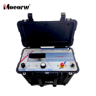
Product Overview
The MOEORW-WHVA30 is a 0.1Hz Very Low Frequency AC hipot tester integrated with Tan Delta dielectric loss measurement and DC withstand voltage capabilities. Designed as a portable, all-in-one diagnostic instrument, it addresses the challenge of testing high-capacitance electrical equipment such as power cables, large generators, motors, and power capacitors, where conventional power-frequency AC testing would require excessively bulky and costly transformers.
By employing 0.1Hz ultra-low frequency technology, the HVA30 reduces the required test power capacity to approximately 1/500 of that at 50/60Hz, enabling a compact 19.5 kg form factor without compromising test equivalence to power-frequency AC. The unit integrates a 7-inch capacitive touchscreen, a built-in thermal printer, and an ARM7 microcontroller with high-speed ADC acquisition, delivering fully automated test sequences from ramp-up to measurement and protection.
The WHVA30 complies with the Chinese power industry standard DL/T849.4-2004 General Technical Conditions for Very Low Frequency High Voltage Generators and aligns with international practices recommended by the IEC for VLF testing.
Technical Specifications
|
Model |
MOEORW-WHVA30 |
|
Power supply voltage |
100-240V; 50/60Hz; ±10% |
|
Input power |
400VA |
|
Output voltage [Max.] |
VLF Sinewave: 28kVrms (RMS), 40kVPeak (peak value) VLF Squarewave: 30kV DC [+/-]: +40kV/-40kV |
|
Output voltage [Max.] |
Sinewave: 10mArms Squarewave/DC[+/-]: 14.5mA |
|
Output frequency |
0.01Hz-0.1Hz in 0.01Hz increments |
|
Frequency optimization |
have |
|
Output load capacity |
At rated voltage of 0.1Hz: 0.5µF; at low frequency or low voltage: 12µF |
|
Measurement |
Current resolution: 1µA±1% Voltage resolution: 0.1kV±1% Capacitor resolution: 0.1nF-20µF Resistance: 0.1MΩ-20GΩ |
|
Output task |
continuous |
|
Test mode |
Manual or Automatic |
|
Output mode (Unrelated to load, symmetrical) |
VLFACSinewave VLFACSquarewaveDC[+or–polarity] VacuumBottleTesting |
|
Arc Management Mode |
Troubleshooting method: Arc combustion Fault tripping method: Arc extinguishing tripping |
|
PC Interface |
RS232 (standard) USB flash drive module (optional) |
|
Record storage |
Built-in memory: Up to 50 reports, 40 test sequences USB Flash Drive: Unlimited Memory |
|
Computer software (including) |
HVRControlCenter for WindowsXP/Vista |
|
Weight |
19.5kg |
|
Size (Controller not included) |
430mmx360mmx250mm(17"x14"x10") |
|
Environment |
Storage temperature: -25°C to 70°C (-13°F to 158°F) Operating temperature: -5°C to 45°C (23°F to 113°F) Humidity: 5-85% (non-condensing) |
Key Features and Benefits
1. Integrated Tan Delta and Insulation Diagnostics
The HVA30 measures dielectric loss angle tangent, Tan δ, to assess insulation aging. By analyzing the ratio of resistive leakage current to capacitive current under 0.1Hz excitation, the instrument provides quantitative indicators of insulation degradation. Test results are compared against established thresholds, including standard deviation, slope, and mean values, to determine insulation condition as normal, recommended for follow-up, or requiring immediate action.
2. Advanced Digital Control Architecture
Built around a high-performance ARM7 microcontroller with high-speed ADC acquisition circuitry, the HVA30 implements digital frequency conversion and closed-loop negative feedback control. This design eliminates capacitive rise effects and ensures stable, distortion-free sinusoidal output across the full load range.
3. Fully Automated Test Sequences
The instrument manages the complete test cycle: self-diagnostic check, voltage ramp-up, constant-amplitude output, automatic shutdown, and capacitive discharge. Operators simply set test parameters, including voltage, frequency, duration, and protection limits, and initiate the sequence via the touchscreen.
4. Multi-Mode Output Flexibility
Supports VLF AC sinewave, VLF AC squarewave, DC +/− polarity, and vacuum bottle testing modes. Frequency selection from 0.01 Hz to 0.1 Hz in 0.01 Hz increments allows optimization for different test standards and load conditions.
5. Comprehensive Protection System
Multi-tier protection includes over-voltage protection, high-voltage-side over-current protection, and low-voltage-side over-current protection, with trip response time ≤10 ms. The controller connects to the high-voltage generator via optical isolation, ensuring operator safety.
6. On-Site Data Management
Equipped with a 7-inch capacitive touchscreen displaying real-time voltage and current waveforms and test data. Built-in thermal printer produces test reports immediately. Internal memory stores up to 50 test reports and 40 test sequences; optional USB flash drive expands storage indefinitely. PC software, HVR Control Center, enables data export, analysis, and report generation.
7. Rugged, Portable Design
Integrated construction with carrying handle; weighs only 19.5 kg and measures 430×360×250 mm. Operates reliably in field environments from −5°C to 45°C.
Applications
Power Cable Testing
XLPE and PILC cables up to 35kV class
Commissioning tests: 60 minutes at 3U₀
Preventive maintenance: 15 minutes at 3U₀
Simultaneous Tan Delta measurement for insulation condition assessment
Generator and Motor Testing
Medium and large generators, synchronous motors
Stator winding insulation withstand voltage and dielectric loss diagnostics
Single-phase capacitance values per table in the manual
Power Capacitors
High-capacitance load testing at reduced power requirements
Dielectric loss measurement for aging assessment
Vacuum Bottle Testing
Dedicated output mode for vacuum interrupter integrity verification
Standard Accessories
|
Item |
Quantity |
|
MOEORW-WHVA30 Main Unit |
1 |
|
High-Voltage Output Cable |
1 set |
|
Grounding Cable |
1 |
|
Power Cord 100–240V |
1 |
|
RS232 Communication Cable |
1 |
|
HVR Control Center Software CD |
1 |
|
Discharge Rod |
1 |
|
Test Leads and Clips |
1 set |
|
Spare Fuses |
2 |
|
Product Manual |
1 |
Working Principle
VLF Generation
The WHVA30 employs digital frequency conversion technology to generate a 0.1Hz or variable frequency high-voltage sinusoidal waveform from standard AC mains input. By reducing the test frequency to 1/500 of power frequency, the reactive power demand of capacitive loads decreases proportionally, allowing a lightweight design that replaces massive series-resonant or power-frequency test transformers.
Tan Delta Measurement
For a cable under test, the insulation can be modeled as a parallel combination of insulation resistance, R, and capacitance, C. Under AC excitation:
- Resistive current, or leakage, is in phase with voltage and indicates insulation degradation.
- Capacitive current leads voltage by 90° and is proportional to cable length and type.
The loss angle δ is the angle whose tangent equals the ratio of resistive to capacitive current:
Tan δ = I_resistive / I_capacitive
A higher Tan δ value indicates greater insulation loss and accelerated aging. The HVA30 measures Tan δ at multiple voltage levels, 0.5U₀, 1.0U₀, and 1.5U₀, during the test sequence and compares results against standard criteria for pass or fail assessment.
Arc Management
The system incorporates arc-burning regulation and arc-extinguishing trip modes, allowing controlled fault conditioning or immediate trip upon arc detection, protecting both the equipment under test and the tester itself.
Routine Maintenance
Monthly Power-On in Humid Climates
In regions with high humidity or during rainy seasons, if the instrument is stored for extended periods, it is recommended to power on the unit for approximately two hours each month to dissipate internal moisture and protect electronic components.
Storage Conditions
Store in a ventilated indoor environment at −20°C to +60°C, relative humidity below 85%, free from corrosive gases. Do not place directly against floors or walls.
Transportation
Use original packaging with foam padding. Protect from rain, dust, and mechanical impact during transport.
Fuse Replacement
The power inlet incorporates a fuse holder. If the screen does not illuminate upon power-on, check and replace the fuse with the specified rating.
Troubleshooting Guide
|
Issue |
Possible Cause |
Action |
|
Screen does not power on |
Blown fuse |
Check and replace fuse per specification |
|
No Load message displayed |
No capacitive load detected or high-voltage unit not connected |
Verify connections to test specimen or high-voltage section |
|
Over-voltage trip |
Output voltage exceeded set limit |
Check set voltage limit; inspect test specimen for insulation breakdown |
|
Over-current trip |
Output current exceeded set limit |
Verify load capacitance calculation; check for insulation faults; adjust current limit setting |
|
Unstable output or waveform distortion |
Possible insulation defect in test specimen |
Stop test immediately; inspect specimen; clean and dry if surface contamination suspected |
Frequently Asked Questions
Q: What is the advantage of 0.1Hz VLF testing over DC or power-frequency AC testing?
A: VLF testing provides equivalent insulation stress to power-frequency AC but requires only about 1/500 of the power capacity, enabling portable equipment. Unlike DC testing, which can cause space charge accumulation and permanent insulation damage, VLF AC applies bidirectional stress that better simulates service conditions. DC hipot is no longer recommended by recent Chinese preventive test standards.
Q: How do I determine the test voltage for a cable?
A: For cables rated at voltage U₀, the phase-to-ground voltage, the test voltage is 3U₀ for VLF AC testing. For example, a 10kV cable with U₀ = 8.7kV requires a test voltage of 26kV peak. Refer to the voltage rating table in the manual for specific cable types and standards.
Q: How do I set the over-current protection value?
A: Estimate the capacitive current using: I₀ = 2πfCU, where C is cable capacitance in µF, f = 0.1 Hz, and U is test voltage in kV. Multiply by a reliability factor k = 1.5 for the protection setting.
Q: How long should the test last?
A: For commissioning or acceptance tests: 60 minutes. For preventive maintenance: 15 minutes. These durations align with DL/T standards for XLPE cables.
Q: What does the Tan Delta measurement tell me?
A: Tan δ quantifies the ratio of resistive leakage current to capacitive current in the insulation. A rising Tan δ indicates increasing dielectric loss and insulation aging. The HVA30 evaluates multiple parameters, including standard deviation, slope between 0.5U₀ and 1.5U₀, and mean value at U₀, against threshold criteria to classify insulation condition.
Q: Can the HVA30 test loads other than cables?
A: Yes. The unit is suitable for generators, motors, power capacitors, and vacuum bottles. Output load capability extends to 12 µF at lower frequencies or voltages.
Q: What should I do if the test specimen fails during the test?
A: If destructive discharge occurs, the test is considered failed. If abnormal waveform, current surge, smoke, or flashover is observed, stop immediately and investigate. If caused by surface contamination or humidity, clean and dry the specimen before retesting.
Hot Tags: integrated vlf‑tan delta diagnostic tester, China integrated vlf‑tan delta diagnostic tester manufacturers, factory, 40kV Ultra low Frequency High Voltage Generator, 60kV Ultra low Frequency High Voltage Generator, Integrated VLF Hipot Tester, No Partial Discharge Power Frequency Test Device, vlf ac hipot test set, VLF High Voltage Generator With Tan Delta