Product Introduction
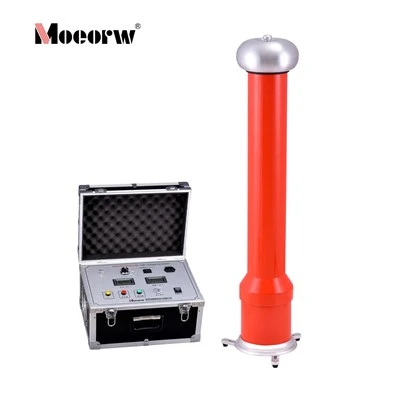
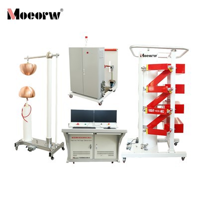
The MOEORW-WGL150 Impulse Current Generator is an integrated test device specifically designed for high-voltage testing in power systems. It is primarily used to generate standard lightning impulse current waveforms for residual voltage tests and withstand voltage tests on arresters, insulators, air gaps, bushings, power transformers, GIS and other power transmission and transformation equipment. The device features an aluminum alloy frame structure with a maximum charging voltage of 150kV. The main body and control console are separately designed, balancing portability with operational safety. The main body adopts an asymmetrical voltage-doubling charging method, consisting of two metal-enclosed pulse capacitors, a pair of triggering spark gaps, and charging/discharging resistors to form a standard circuit. Wave-shaping resistors and inductors can be flexibly configured according to test requirements to accommodate various load characteristics. The control console, built around a Siemens PLC, integrates charging control, triggering control, voltage and current display, safety interlocking and fault diagnosis. Together with a Rogowski coil and residual voltage divider, it forms a complete measurement system.
Product Parameter (specification)
|
Parameter |
Specification |
|
Stage Voltage |
±150kV |
|
Lightning Impulse Current Waveform |
(7~9)/(18~22)µs, peak current 10/20±10% kA |
|
Withstand Impulse Current Waveform |
(3.6~4.4)/(9~11)µs, peak current 100±10% kA |
|
Residual Voltage Measurement Range |
≤50kV |
|
Charging Voltage Setting Range |
0~150kV, operating voltage 30.0~150kV |
|
Charging Voltage Adjustment Accuracy |
0.1kV |
|
Charging Voltage Instability |
<±0.5% |
|
Deviation from Set Voltage |
≤±1% |
|
Voltage Rise Time Setting Range |
30~190s, adjustment accuracy 1s |
|
Impulse Test Count Setting Range |
0~99 times, adjustment accuracy 1 time |
|
Alarm Delay |
2s |
|
Continuous Operation Condition |
≥75% Un: charge/discharge every 120s;<75% Un: charge/discharge every 60s |
|
Altitude |
≤1000m |
|
Ambient Temperature |
-10℃~+45℃ |
|
Relative Humidity |
≤90% |
|
Charging Transformer Rating |
8kVA, primary 380V / secondary 80kV |
|
High-Voltage Silicon Rectifier Specification |
2DL-300kV/300mA |
|
Grounding Resistance Requirement |
≤0.5Ω |
Product feature
1. High-Precision Waveform Output Ensuring Reliable Test Data
The device employs a Siemens PLC-based intelligent constant-current charging control system, combined with 12-bit high-speed high-precision digital processing modules and software-hardware redundancy technology, achieving charging voltage tracking accuracy better than ±0.5%, significantly exceeding the national standard requirement of ±1% instability. The DC resistive voltage divider features an oil-immersed insulated housing with a grounded shielding ring, effectively eliminating stray capacitance interference on measurement accuracy. This precision ensures consistent waveform output across batch comparisons and type tests, preventing test misjudgments caused by equipment fluctuations.
2. Multi-Layer Redundant Safety Protection System
All PLC inputs and outputs are isolated through optoelectronic and switch isolation technologies, keeping the control circuit in a fully isolated low-voltage state at all times. Even in the event of breakdown discharge on the high-voltage side, strong transient electromagnetic interference cannot penetrate the control core. An emergency stop button is provided at the hardware level, operating directly through hardware circuitry independent of the PLC with highest priority, instantly cutting off the main circuit power when pressed. Upon test completion, the automatic grounding device engages through an electromagnet-driven mechanism to ground the charging equipment, while the main capacitors are automatically short-circuited and discharged, eliminating residual voltage shock hazards. The door interlock ensures the system automatically trips if the safety door is opened during testing.
3. Integrated Measurement and Control Design for Enhanced Efficiency
The system integrates charging control, triggering control, polarity switching, data acquisition and waveform analysis into a single operator interface. Before testing, the operator simply sets the charging voltage (30.0~150kV adjustable), discharge count (0~99 times adjustable), voltage rise time (30~190s adjustable) and interval time on the console touchscreen. The system then automatically completes the entire sequence of constant-current charging, voltage-reach indication, ignition triggering and data recording. Polarity switching is performed automatically by a drive motor with real-time status display. When paired with a Tektronix oscilloscope and fiber-optic data transmission, waveforms are automatically saved and standard test reports can be generated and printed. In fully automatic mode, operators only need to set parameters and monitor operation, significantly reducing total test duration.
4. Broad Operating Condition Adaptability
The charging transformer adopts an oil-immersed insulated housing design with a primary voltage of 380V, secondary voltage of 80kV and a power rating of 8kVA, ensuring thermal stability during prolonged continuous operation. The aluminum alloy chassis structure combines mechanical strength with lightweight design, enabling normal operation at altitudes up to 1000m, temperatures ranging from -10℃ to +45℃ and relative humidity up to 90%. Regarding condensation on insulating components caused by temperature differentials, the manual explicitly requires a 12-hour resting period before use when temperature differences exceed 25℃, further safeguarding equipment integrity through operational procedures.
5. Strong Anti-Interference Design
The console extensively employs optoelectronic and switch isolation technologies. All analog signal acquisitions - including primary voltage and current of the charging transformer and main body charging voltage - are processed through 12-bit high-speed digital processing modules, with signal transmission via shielded cables into the console. Fiber-optic communication between the oscilloscope and computer completely eliminates ground loop interference paths. Even in strong transient field environments generated by 100kA discharge currents, the measurement system stably records waveform parameters without data loss or control drift.
6. Modular Structure and Maintainability Design
The main body consists of two metal-enclosed pulse capacitors, a pair of triggering spark gaps, charging and discharging resistors forming a standard discharge circuit. Wave-shaping resistors and inductors can be flexibly configured according to specimen requirements. Internal PLC modules, transmitters and trigger boards in the console are all standard industrial components, enabling rapid fault location and replacement. The spark gap drive mechanism is equipped with limit detection, providing timely alarms in case of jamming or abnormalities. The modular design significantly reduces downtime and enhances equipment availability.
Product Application
The MOEORW-WGL150 Impulse Current Generator is applicable to the following specific test scenarios:
Arrester Factory and Type Testing:Performs lightning impulse current residual voltage tests and withstand voltage tests on metal-oxide surge arresters to evaluate their operating characteristics and energy withstand capability under lightning overvoltages. This is the device's core application, compliant with GB/T 11032 and IEC 60099-4 standards.
Insulator String Impulse Performance Testing:Evaluates the surface flashover characteristics and mechanical strength of insulators under lightning impulse currents, providing experimental data for external insulation design of transmission lines.
Air Gap Discharge Characteristic Research:Simulates air gap breakdown tests under lightning overvoltages in laboratory settings to study discharge patterns under various electrode configurations, gap distances and meteorological conditions.
Bushing and GIS Equipment Testing:Conducts impulse current tests on power transformer bushings, GIS bushings and internal insulation structures to verify insulation coordination reliability under system transient overvoltages.
Power Transformer Withstand Verification:Performs impulse current injection at transformer neutral points or winding terminals to verify insulation margin when subjected to lightning wave intrusions.
Basic Research in Scientific Institutions:Serves as a standard impulse current source in high-voltage laboratories for fundamental research on material breakdown characteristics, discharge physics and overvoltage protection technologies.
Product Package Contents
The complete MOEORW-WGL150 Impulse Current Generator consists of the following four major components, ready for installation and use upon delivery:
1. Charging Device
Mounted on a manually movable aluminum alloy chassis, comprising:DC resistive voltage divider (oil-immersed insulated housing with grounded shielding ring), bi-directional SCR and constant-current device, charging transformer (insulated housing oil-immersed design, primary 380V/secondary 80kV, 8kVA rating), high-voltage silicon rectifier (2DL-300kV/300mA type, supported by insulating tubes, polarity reversal changes output positive/negative), protection resistor (approximately tens of kilo-ohms), automatic grounding device (electromagnet-driven contact mechanism, automatically grounds after test completion).
2. Impulse Main Body
Insulated pillar tank-type structure, comprising:main capacitors (two metal-enclosed pulse capacitors), charging resistor, discharging resistor, wave-shaping resistors and inductors (flexibly configurable to meet various specimen test requirements), triggering spark gap (a pair, pneumatically driven), ignition device, aluminum alloy chassis.
3. Control Console
Portable control console, comprising:Siemens PLC control system, touchscreen operator interface, digital voltage/current display, emergency stop button (hardware direct control with highest priority), polarity switching motor control, charging voltage setting and display, fault diagnosis and alarm module.
4. Measurement System
Comprising:Rogowski coil (for impulse current measurement), residual voltage resistive divider (for residual voltage measurement), measurement cables, oscilloscope interface and fiber-optic communication module (for isolated data transmission between oscilloscope and computer).
FAQ
Q: Are you a manufacturer or a trading company?
A: We are a direct manufacturer specializing in high-voltage testing equipment. We have our own R&D team and production facility, which allows us to offer factory-direct pricing and strict quality control.
Q: What is your warranty and after-sales policy?
A: All units come with a 12-month warranty. After the warranty expires, we provide lifetime technical support and paid maintenance services.
Q: Do you support English language interfaces?
A: Yes, our standard models feature English keyboards, software, and user manuals. If you require other languages, please contact us to check availability for customization.
Hot Tags: impulse current test device, China impulse current test device manufacturers, factory