


MOEORW-WXL778 Variable Frequency Series Resonance Test systems
A professional high-voltage withstand voltage test equipment with 1350kVA/270kV, specially designed for the detection of main electrical equipment in power systems
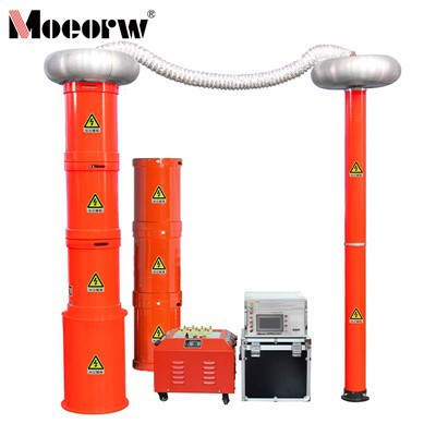
AC Resonant Test System 270kV Light and portable as a whole, with multiple operation modes to flexibly adapt to on-site needs
For high-voltage test departments at prefecture, city and county levels, and power installation/maintenance engineering units; used for AC withstand voltage detection of medium and high-voltage equipment such as cables, transformers and generators
Accurately complete the withstand voltage test of equipment and ensure the safe and stable operation of power equipment
Product Introduction
Resonant AC Test Systems This device is primarily designed and manufactured for AC withstand voltage testing of all major electrical equipment, including 110 kV and 35 kV cables, generators, and power transformers and busbar switches rated at 35 kV and below. The reactors are designed as multiple separate units, enabling the device to meet the testing requirements for both high-voltage, low-current equipment and low-voltage AC withstand voltage tests, such as those for 10kV cables. With its wide range of applications, it is an ideal withstand voltage testing device for high-voltage testing departments at the provincial, municipal, and county levels, as well as for power installation, maintenance, and testing engineering units.
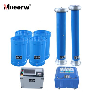
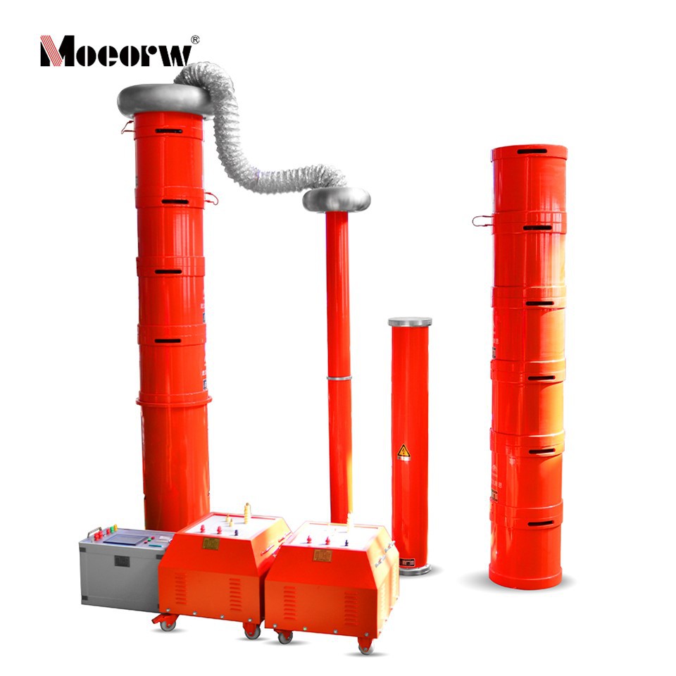
The unit primarily consists of a frequency conversion power supply, an excitation transformer, reactors, and a capacitive voltage divider.
1.1 Advantages of Series Resonance in Power Systems
1. The required power supply capacity is significantly reduced. A series resonance power supply utilizes the resonance between the resonance reactor and the capacitance of the test specimen to generate high voltage and high current. In the entire system, the power supply only needs to provide the active power consumed by the system; therefore, the power required for the test is only 1/Q of the test capacity.
2. The weight and volume of the equipment are significantly reduced. In a series resonance power supply, not only are bulky high-power voltage regulators and conventional high-power power-frequency test transformers eliminated, but the resonance excitation power supply also requires only 1/Q of the test capacity. This results in a significant reduction in system weight and volume, typically ranging from 1/10 to 1/30 that of conventional test equipment.
3. Improved output voltage waveform. The resonant power supply functions as a resonant filter circuit, which reduces output voltage waveform distortion and produces a high-quality sine wave. This effectively prevents harmonic peaks from causing accidental breakdown of the test specimen.
4. Prevention of damage to the fault point caused by high short-circuit currents. In a series resonance state, when the insulation weakness of the test specimen is broken down, the circuit immediately detunes, and the loop current rapidly drops to 1/Q of the normal test current. In contrast, when conducting withstand voltage tests using parallel resonance or a test transformer, the breakdown current immediately increases by dozens of times. Comparing the two, the short-circuit current differs from the breakdown current by a factor of hundreds. Therefore, series resonance can effectively locate insulation weaknesses without the risk of high short-circuit currents damaging the fault point.
5. No recovery overvoltage occurs. When the test specimen breaks down, the high voltage disappears immediately due to the loss of resonance conditions, and the arc is instantly extinguished. Furthermore, the process of re-establishing the recovery voltage is very long, making it easy to disconnect the power supply before the flashover voltage is reached again. This voltage recovery process is an intermittent oscillation process involving energy accumulation; it is prolonged, and no recovery overvoltage occurs.
Product Parameter (specification)
|
Technical Specifications |
|
|
1. Rated Voltage |
27 kV-Suitable for AC withstand voltage testing of 10 kV cables; 54 kV-Suitable for AC withstand voltage testing of 35 kV cables and 10 kV systems; 108 kV-Suitable for AC withstand voltage testing of 35 kV systems; 135 kV-Suitable for AC withstand voltage testing of 110 kV cables; 270 kV-Suitable for AC withstand voltage testing of 110 kV systems; |
|
2. Output voltage waveform distortion rate |
<1.0% |
|
3. Permissible continuous operating time |
30 minutes of continuous operation under rated conditions; 60 minutes of continuous operation when testing 35 kV cables |
|
4. Device power factor |
Q > 50 |
|
5. Power factor at full load during thermal power generator testing |
Q > 10 (load-dependent) |
|
6. Power factor at full load during cable testing |
Q > 30 (load-dependent) |
|
7. Power factor at full load during main transformer testing |
Q > 30 (load-dependent) |
|
8. Power factor at full load during GIS, switchgear, and other equipment testing |
Q > 50 (load-dependent) |
|
9. Input power supply |
Single-phase 380 V |
|
10. Frequency adjustment range |
20 Hz to 300 Hz |
|
11. System measurement accuracy |
1.5% |
|
12. The device features protection functions such as overvoltage, overcurrent, and zero-position start |
|
|
2.3 Standards Compliance |
|
|
"Standard for Acceptance Tests of Electrical Equipment in Electrical Installation Projects" |
GB50150-2006 |
|
"High-Voltage Resonance Test Equipment" |
DL/T 849.6-2004 |
|
"Reactors" |
GB10229.88 |
|
"Regulations for Preventive Testing of Power Equipment" |
DL/T596-1996 |
|
"Coupling Capacitors and Capacitive Voltage Dividers" |
IEC358(1990) |
|
2.4 Main Configuration and Technical Parameters of the Equipment |
|
|
1. One Variable Frequency Power Supply |
|
|
Rated Power |
40 kVA; |
|
Input Voltage |
380 V ±10% 45–65 Hz |
|
Output Voltage |
0–400 V adjustable |
|
Output Voltage Frequency |
30–300 Hz |
|
Adjustable in 0.1 Hz increments |
|
|
Frequency Instability |
≤0.02% |
|
Output Current |
0–100 A |
|
High-Voltage Reactors (10 units total) |
27 kV/5 A |
|
Rated Operating Voltage |
27 kV |
|
Rated Operating Current |
5 A |
|
Rated Inductance |
25 H |
|
Continuous Operating Time |
60 min |
|
Temperature Rise |
Less than 60°C |
|
Operating Frequency |
30–300 Hz |
|
Excitation Transformers (2 units) |
|
|
Rated Capacity |
20 kVA |
|
Input voltage |
400 V |
|
Output voltage |
4/8/16 kV; 4 kV is used for AC withstand voltage tests on cables rated below 35 kV; 8 kV is used for AC withstand voltage tests on 110 kV cables and 35 kV substations; 16 kV is used for AC withstand voltage tests on 110 kV and 220 kV substations.O |
|
One capacitive voltage divider |
270 kV pure capacitive type |
|
Internal capacitance |
1000 pF |
|
Operating frequency |
30–300 Hz |
|
Uncertainty |
1.5% |
|
Rated voltage |
135 kV/2000 pF, 270 kV/1000 pF |
|
One compensation capacitor |
160 kV pure capacitive type |
|
Internal capacitance |
20,000 pF |
|
Operating frequency |
30–300 Hz |
|
Rated voltage |
160 kV/20,000 pF |
Product feature and application
1. The device features protection functions such as overvoltage, overcurrent, zero-voltage startup, and system detuning (flashover). The overvoltage and overcurrent protection thresholds can be adjusted according to user requirements. When a flashover occurs, the flashover protection is triggered and records the flashover voltage value for test analysis.
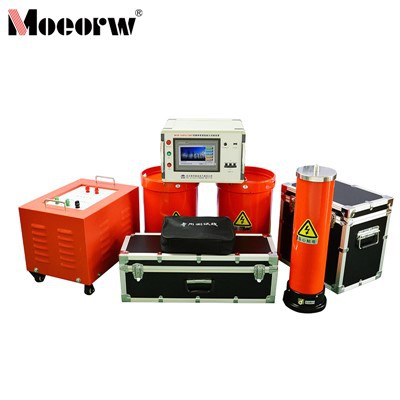
2. Each component of the unit is lightweight, with a maximum weight of no more than 40 kg, making it convenient for on-site use.
3. The unit offers three operating modes, allowing users to flexibly select the appropriate mode based on on-site conditions and thereby increase testing speed.
4. The operating modes are: Fully Automatic Mode, Manual Mode, and Automatic Tuning with Manual Voltage Increase Mode.
5. Data can be stored, with each entry assigned a numerical ID for easy identification and retrieval.
6. During automatic frequency sweeping, the starting frequency can be set arbitrarily within the specified range, and the sweeping direction can be selected as either upward or downward. Simultaneously, the large LCD screen displays the scanning curve, allowing users to intuitively determine whether the resonance point has been found.
7. Utilizing DSP platform technology, functions can be easily added or removed and the system upgraded according to user needs, while also making the human-machine interface more user-friendly.
Prodection details
**Resonant AC Test Systems** of various medium- and high-voltage electrical main equipment in power systems. Suitable for high-voltage testing departments at the provincial, municipal, and county levels, as well as power installation, maintenance, and testing engineering units.
Main Test Objects
1. Cross-linked polyethylene power cables of various specifications at 110 kV, 35 kV, and 10 kV
2. Main power transformers rated at 110 kV and below
3. 110kV substation systems
4. Major electrical equipment such as generators, GIS equipment, busbars, and switches
Company Qualifications
Hot Tags: variable frequency series resonance test systems, China variable frequency series resonance test systems manufacturers, factory, 270kVA 270kV Series Resonance Test Device, 540kVA 270kV Series Resonance Test Device, 54kVA 54kV Series Resonance Test Device, Lightweight Variable Frequency Resonant Systems, Series Resonant Test Set, Variable Frequency Series Resonance Test Systems