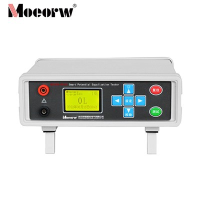
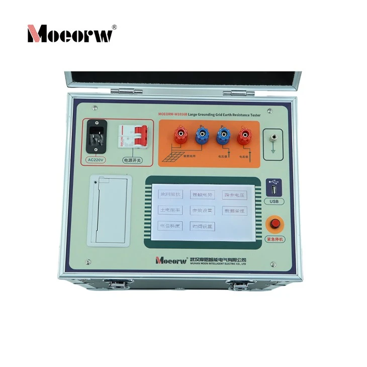
Product Introduction
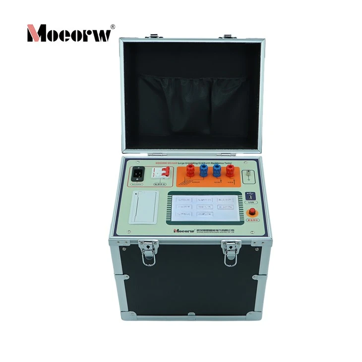
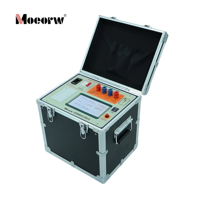
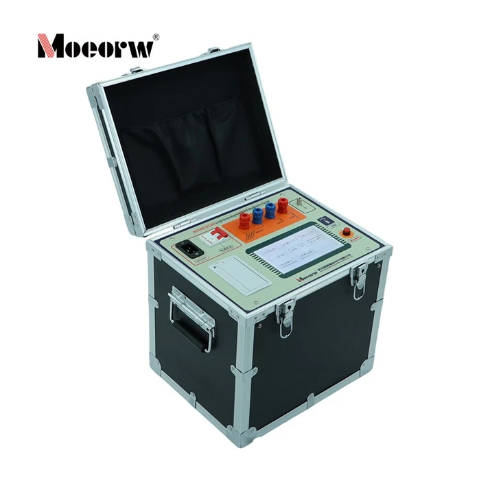
The MOEORW-W1016B Large-Scale Grounding Grid Earth Resistance Tester is a new generation of high-precision, integrated variable-frequency testing equipment developed by Wuhan Moen Intelligent Electric Co., Ltd. This instrument is specifically engineered for substation environments, power plants, and other industrial sites where strong power-frequency electromagnetic field interference makes accurate testing a critical challenge.
Featuring an all-in-one integrated structure, the device houses a built-in variable frequency power module and a high-speed processor core. By outputting a continuous, adjustable variable-frequency test current at 45Hz or 55Hz and leveraging state-of-the-art digital filtering technology, it completely bypasses power-frequency interference. Lightweight, compact, and highly reliable, it is the ideal professional solution for measuring the characteristic parameters of large and medium-sized grounding grids.
Product Features & Core Advantages
- Advanced Variable Frequency & Anti-Interference Technology: The built-in module delivers test currents at alternative frequencies (e.g., 45Hz/55Hz). Combined with advanced digital filtering software algorithms, it effectively filters out grid harmonics and electromagnetic noise, achieving exceptionally high accuracy.
- High-Speed DSP Processing Core: Equipped with a professional-grade DSP (Digital Signal Processor), the instrument delivers massive computing power, guaranteeing instantaneous, precise data analysis under complex conditions.
- Intelligent Full-Process Measurement and Control: Supported by its high-performance CPU, the device automatically evaluates the loop impedance of the current circuit and autonomously dynamically scales the variable-frequency output current (up to 5A) without any manual intervention.
- Extra-Large Full-Touch Graphic LCD Panel: The user interface features an intuitive, large-screen graphic touch display. Each operational step is clearly mapped out, allowing operators to run complete tests easily without requiring exhaustive professional training.
- One-Touch Emergency Stop for Ultimate Safety: Designed with a dedicated "Emergency Stop" physical button on the panel. In case of any unexpected on-site emergency, operators can instantly cut off all output power without disconnecting the main input power supply, safeguarding personnel and field assets.
- Massive Storage & PC Data Management Portability: Includes a built-in real-time clock and high-capacity memory capable of saving 100 groups of historical data. Data can be easily exported via a USB flash drive to a PC for further analysis, logging, and generating comprehensive inspection reports
Product Parameter / Specification
|
Parameter Item |
Technical Specifications & Details |
|
Model Number |
MOEORW-W1016B |
|
Resistance Range |
0.001 Ω ~ 2K Ω |
|
Output Test Current |
1A ~ 5A (Continuously Adjustable) |
|
Output Voltage |
0V ~ 100V |
|
Rated Output Power |
500W |
|
Test Power Frequency |
50Hz/60Hz Single Frequency; 45/55, 55/65, 47.5/52.5, 57.5/62.5Hz Auto Dual Frequency |
|
Measurement Accuracy |
Grounding Impedance: ±(1%×reading + 0.002Ω); Impedance Angle: ±(1%×reading + 0.02°) |
|
Resolution |
Grounding Impedance: 0.0001 Ω; Impedance Angle: 0.0001° |
|
Anti-Interference Principle |
Variable Frequency Method + High-End Digital Filtering |
|
Operating Conditions |
Ambient Temperature: -10℃ ~ 40℃; Ambient Humidity: RH < 80% |
|
Power Supply |
AC 220V ± 10% (Generator power supply permitted) |
|
Memory Capacity |
Stores up to 100 groups (Supports USB storage expansion) |
|
Dimensions & Weight |
Main unit: 12Kg; Dimensions: 370(L) × 295(W) × 225(H) mm |
Product Applications
The MOEORW-W1016B is widely trusted across sectors including electrical power utilities, petroleum, petrochemical, telecommunications, national defense, railways, airports, and large mining enterprises.
Substation & Power Plant Commissioning: Assessing grounding grid health, grounding impedance, and routine safety grid audits under heavy running electromagnetic interference.
Large-Scale Grounding Grid Handover Inspections: Highly accurate field assessments of touch voltage, step voltage, and ground surface potential gradient curves.
Soil Resistivity Surveys: Conducting geological soil resistivity screening (using the Four-Electrode method) for prospective substation sites and massive earthwork engineering.
Multi-Dimensional Measurement Metrics
Moving far beyond basic single-resistance testing, this instrument evaluates and delivers a thorough technical breakdown of the earth grid's structural parameters, providing engineers with robust analytical data:
- Grounding Impedance (Z)
- Pure Resistance Component (R) & Pure Inductive Reactance Component (X)
- Impedance Angle (Φ)
- Touch Potential / Touch Voltage (Uj)
- Step Voltage (Uk)
- Soil Resistivity
- Surface Potential Gradient Curves
Scientific On-Site Wiring Configurations
To eliminate mutual inductance between long wiring leads, the MOEORW-1016B accommodates the two standard field wiring methods seamlessly:
Parallel Wiring Method: Incorporates the common 0.618 layout where voltage and current lines run parallel. Thanks to the tester's internal coupling cancellation firmware, it maintains reliable precision even when space constraints force the lines into close proximity.
Angle Wiring Method (Highly Recommended): The current and voltage wires are extended at an angle (typically an isosceles triangle configuration at a 30° angle). This completely separates the lines physically, eliminating coupling errors and providing optimal baseline measurements.
FAQ
Q1: Why do traditional power-frequency current methods cause massive errors when testing grounding grids?
A: In operational substations, heavy electromagnetic fields induce power-frequency voltages up to several volts onto long voltage testing leads. Because traditional testers use the exact same frequency as the grid (50Hz), it becomes mathematically impossible to completely filter out this ambient background noise from the true test signal, leading to severely skewed or unstable data.
Q2: How does the MOEORW-W1016B successfully eliminate heavy field interference?
A: The tester utilizes a breakthrough Variable Frequency (Heterodyne) Method. It active-shifts its output current to alternative frequencies, such as 45Hz and 55Hz, avoiding the standard 50Hz grid noise. The onboard high-speed DSP processor then uses targeted digital filtering algorithms to extract only the matching 45Hz/55Hz components, cleanly rejecting all grid harmonics, high-frequency transients, and DC bias voltages.
Q3: What are the critical safety guidelines when operating this grounding grid earth tester?
A:
1.Mandatory Frame Grounding: Before powering on, you must ensure that the equipment's dedicated grounding terminal on the panel is securely bonded to a reliable local ground point.
2.High Voltage Warning: During active testing cycles, the red output terminals (C1, C2) can reach voltages up to 100V. Personnel must never touch the terminals or bare wires while a test is active.
3.Step Voltage Guardrail: When executing a test, the tester's safety ground must be tied either directly to terminal P2 or within a strict 1-meter radius around the P1 voltage stake. Connecting it improperly to C2 can cause fatal hardware damage to the internal electronics.
Hot Tags: earth resistance tester for large ground grid, China earth resistance tester for large ground grid manufacturers, factory